Table of Contents
Introduction:
The NE555 Police Light Circuit is a simple and fun electronics project that uses two NE555 timer ICs to simulate the flashing lights commonly seen on emergency vehicles like police cars. This circuit generates an alternating flash pattern with two sets of LEDs, which creates a visual effect similar to police lights.
The NE555 timer ICs, configured in astable mode, drive two separate LED arrays that blink on and off in a synchronized pattern. By adjusting the values of resistors and capacitors in the circuit, the flash rate can be modified to suit different preferences.
This project is ideal for beginners who want to explore the basics of 555 timer circuits, as well as for enthusiasts looking to create eye-catching visual effects. With only a handful of components required, it’s a straightforward and engaging way to learn about timing circuits and LED control.

Component Details:
| S.No | Components | Value | Qty. |
|---|---|---|---|
| 1. | Time IC | NE555 | 2 |
| 2. | Resistor | 820K, 100K, 1k | 1,1,2 |
| 3. | Capacitor | 10uf, 0.1uf | 1,1 |
| 4. | LED | Red, Blue | 6,6 |
| 5. | Power Supply | DC 5V | – |
NE555 Pinout:

Circuit Diagram:
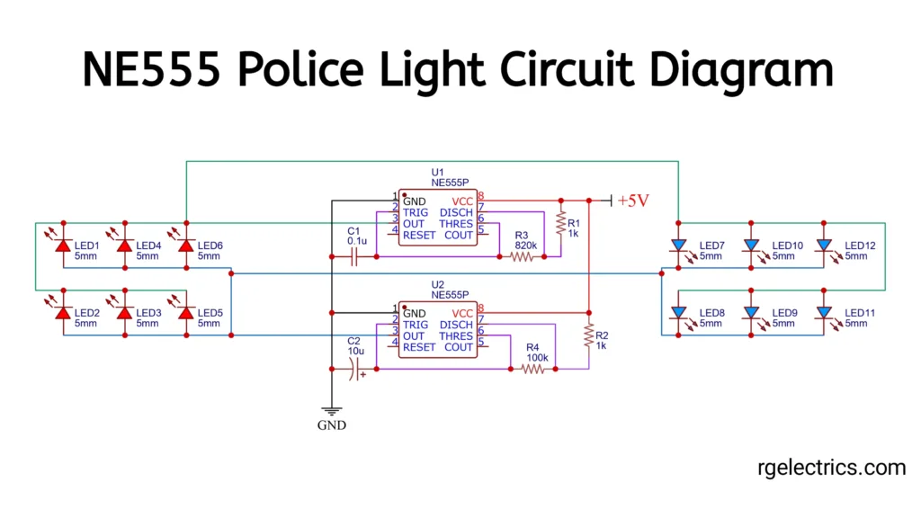
Circuit Explaination:
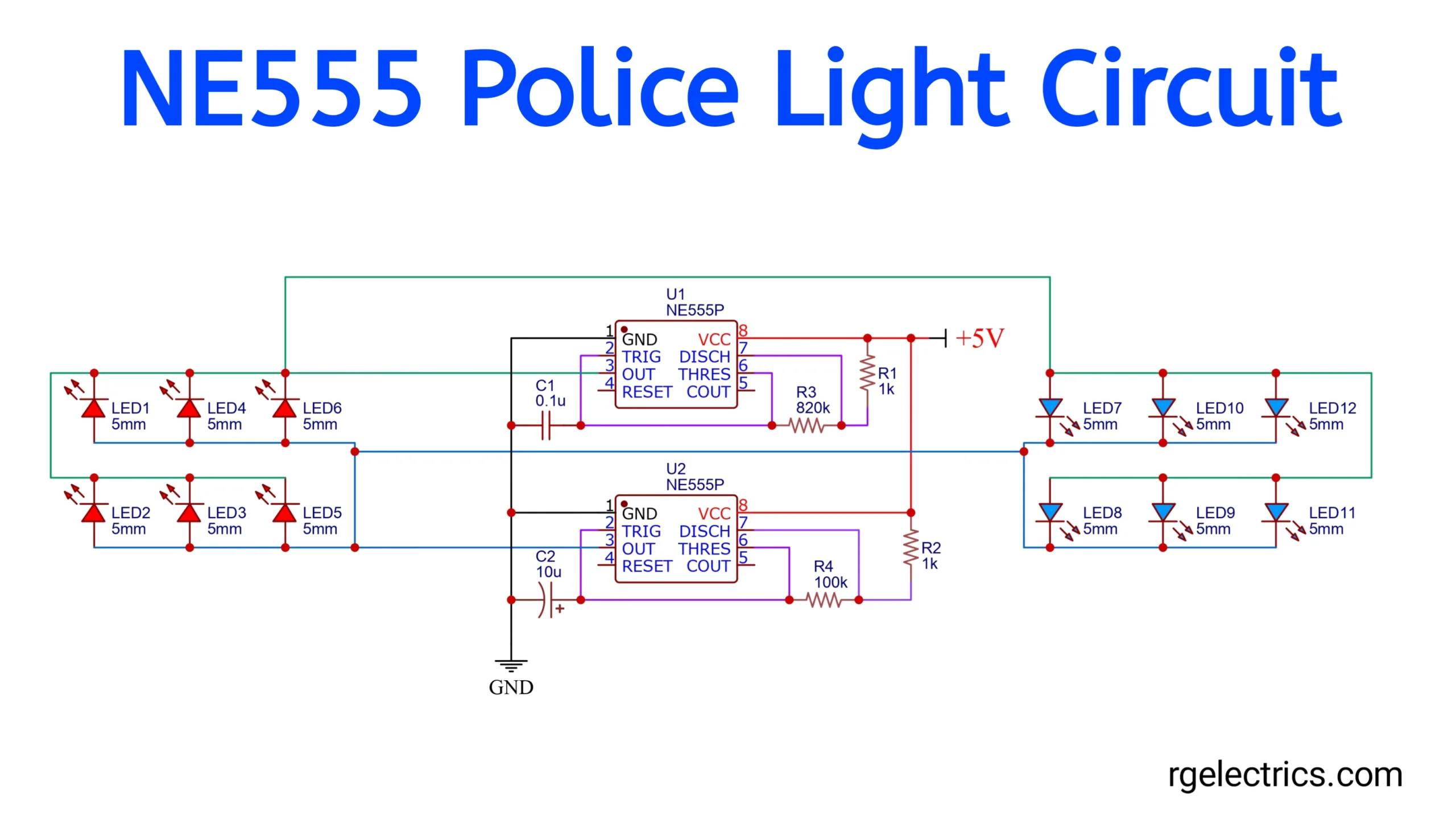
This police light circuit uses two NE555 timer ICs in astable mode to create alternating flashing patterns on two sets of LEDs. Here’s a detailed breakdown of how the circuit works:
1. Power Supply:
- The circuit operates with a 5V DC power supply, connected at the top-right corner. This is a typical low-voltage supply, suitable for battery operation.
- The ground (GND) symbol at the bottom connects the circuit to the negative terminal of the power supply.
2. NE555 Timer ICs (U1 and U2):
- Astable Mode: Both NE555 ICs are configured in astable mode, meaning they constantly oscillate between high and low output states. This oscillation creates the flashing effect.
- Alternating Outputs: Each timer drives one set of LEDs, which will flash alternately due to the phase difference set up by the circuit components.
- Pin Configuration for Astable Mode:
- Pin 1 (GND): Connected to the ground.
- Pin 8 (VCC): Connected to the +5V supply.
- Pin 3 (OUT): This is the output pin where the oscillating signal is sent to the LEDs.
- Pins 6 (THRES) and 2 (TRIG): These pins are connected together in astable mode to form the timing circuit with the resistors and capacitors.
- Pin 7 (DISCH): Connected to resistors to control charging and discharging cycles of the capacitors.
3. Timing Components:
- R1, R3, and C1 (for U1) and R2, R4, and C2 (for U2) are the key components that control the timing and oscillation frequency of each NE555 timer.
- R1 and R3 with C1 set the flash rate for U1.
- R2 and R4 with C2 set the flash rate for U2.
- Capacitors (C1 and C2): Capacitors are used to charge and discharge in each timing cycle, controlling how long each LED group stays on and off.
- Resistors (R1, R2, R3, and R4): These resistors limit the current and help set the timing frequency in conjunction with the capacitors.
4. LED Arrangement and Flashing Pattern:
- The circuit has two LED groups, each controlled by one NE555 IC.
- Group 1 (LED1-LED6) is connected to the output of U1.
- Group 2 (LED7-LED12) is connected to the output of U2.
- Each group has a set of parallel LEDs, simulating one color of a police light.
- Alternating Flashes: When U1’s output goes high, LEDs in Group 1 light up. Meanwhile, U2’s output will be low, keeping LEDs in Group 2 off. When U1 switches to low, U2 goes high, lighting up Group 2 LEDs. This back-and-forth flashing creates the typical alternating police light effect.
5. How the Flashing Pattern Works:
- The NE555 timers U1 and U2 are set with slightly different timing components (resistor and capacitor values), which can lead to a slight delay between their oscillations. This delay causes one group of LEDs to turn on while the other is off, and vice versa, giving the illusion of alternating lights.
- The frequency of the flashing can be adjusted by changing the resistor and capacitor values. A higher resistance or capacitance will result in a slower flashing rate, while lower values will increase the speed.
Summary of Operation:
- The 5V power supply activates both NE555 ICs.
- The timing components (resistors and capacitors) make the NE555 ICs oscillate at a specific frequency, determined by the values of R1, R2, R3, R4, C1, and C2.
- Each NE555 alternately powers a set of LEDs, causing them to flash in a back-and-forth pattern.
- The result is a simple police light effect with alternating LED groups, imitating the flashing lights seen on emergency vehicles.
Applications:
- Model or Toy Police Cars
- Home Security and Warning Systems
- Emergency Warning Signals
- Robotics and Automation Projects
- Educational Purposes

