Table of Contents
Introduction:
The TEA2025 is a versatile dual-channel audio amplifier IC designed for low-power audio amplification, commonly used in portable speakers, radios, and multimedia systems. It can operate in either stereo mode or bridge mode. In stereo mode, the IC amplifies two separate audio channels, making it suitable for driving two speakers. In bridge mode, it delivers a higher output by combining both channels to drive a single speaker.
Operating with a supply voltage typically between 3V and 15V, the TEA2025 provides an output power of around 2W per channel at 12V in stereo mode. The IC integrates internal features such as thermal protection, overvoltage protection, and low distortion to ensure reliable performance.
The amplifier’s input is designed to handle low-level audio signals, which are then amplified to drive speakers. Its external components, such as capacitors and resistors, are used for filtering, decoupling, and adjusting gain. Due to its compact size and minimal external components, the TEA2025 is a cost-effective solution for simple audio amplification applications in consumer electronics.
Component Details:
| S.No | Components | Value | Qty. |
|---|---|---|---|
| 1. | IC | TEA2025 | 1 |
| 2. | Capacitor | 470µF/25V, 100µF/25V, 0.22µF, 0.15µF | 2, 6, 2, 2 |
| 3. | Resistor | 10K | 2 |
| 4. | Speaker | 4 Ohm | 2 |
| 5. | Audio Input | – | – |
| 6. | Power Supply | 12V DC | – |
TEA2025 IC Details:
The TEA2025 is a dual audio power amplifier integrated circuit (IC) designed primarily for low-power applications, such as portable audio devices, radios, and multimedia speaker systems. It can operate in both stereo mode and bridge mode (where both channels are combined to provide more power for a single output).
Key Features of TEA2025:
- Operating Voltage: 3V to 15V, making it versatile for battery-powered devices.
- Output Power: Delivers around 2W per channel in stereo mode when powered with 12V, or up to 4W in bridge mode.
- Low Distortion: Provides clear and clean audio amplification with minimal distortion, making it suitable for high-quality audio systems.
- Thermal and Short-Circuit Protection: Built-in protection mechanisms prevent damage due to overheating or short circuits.
- Minimal External Components: Requires only a few external passive components (resistors and capacitors) for proper operation, simplifying the design process.
Due to its cost-effectiveness, ease of use, and reliability, the TEA2025 is commonly used in compact audio amplification systems where moderate sound output is required.
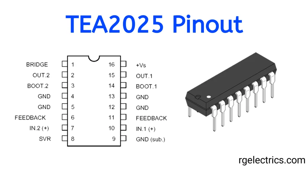
TEA2025 Pin Descriptions:
- BRIDGE (Pin 1): Used to select bridge mode operation for higher output power.
- OUT 2 (Pin 2): Output for the second audio channel (right speaker in stereo mode).
- BOOT 2 (Pin 3): Bootstrap capacitor for the second channel.
- GND (Pin 4): Ground connection.
- GND (Pin 5): Ground connection.
- FEEDBACK (Pin 6): Feedback input for the second channel.
- IN 2 (+) (Pin 7): Non-inverting audio input for the second channel.
- SVR (Pin 8): Supply voltage rejection, used to stabilize the internal reference voltage.
- GND (sub) (Pin 9): Ground connection for the substrate of the IC.
- IN 1 (+) (Pin 10): Non-inverting audio input for the first channel.
- FEEDBACK (Pin 11): Feedback input for the first channel.
- GND (Pin 12): Ground connection.
- GND (Pin 13): Ground connection.
- BOOT 1 (Pin 14): Bootstrap capacitor for the first channel.
- OUT 1 (Pin 15): Output for the first audio channel (left speaker in stereo mode).
- +Vs (Pin 16): Positive voltage supply for powering the IC.
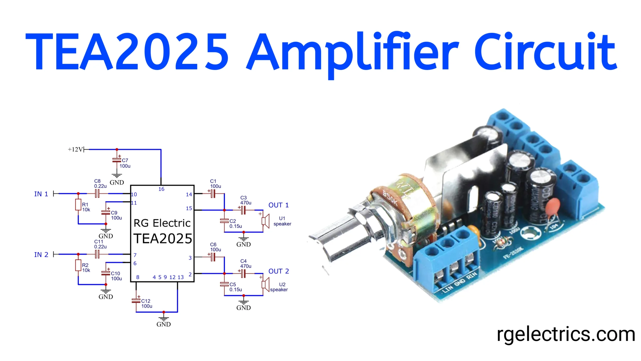
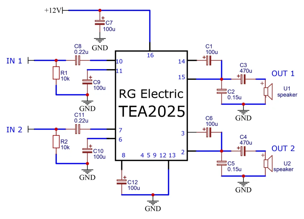
Circuit Diagram:
Working Explaination:
The TEA2025 stereo audio amplifier circuit is designed to amplify two separate audio input signals (IN 1 and IN 2) using TEA2025 IC, which drives two output channels (OUT 1 and OUT 2) connected to the speakers. The circuit is powered by +12V supply, which is stabilized by capacitor C7 (100uF). The audio input is passed through coupling capacitors C8 and C11 (0.22uF each) and resistors R1 and R2 (10kΩ each) to remove the DC components.
The input signals are fed into pins 10 and 7 of TEA2025 for amplification. The output signals from pins 15 and 3 are coupled to the power supply via coupling capacitors C3 and C4 (470uF each) to block any DC offset. Additional capacitors C1 and C6 (100uF each) isolate the power supply. This circuit provides stable and low-distortion audio amplification for stereo applications, making it ideal for small audio devices.
Summary:
This TEA2025 amplifier circuit is a simple, low-cost solution for amplifying two audio channels (stereo). The IC operates with a 12V supply, and minimal external components are required to build the circuit. The coupling capacitors at the input and output stages ensure clean signal transfer, while the feedback and bootstrap configurations improve performance and reduce distortion. The final output is delivered to two speakers, providing stereo sound suitable for small audio devices such as portable speakers, radios, or other multimedia applications.
Applications:
- Portable audio devices (e.g., MP3 players, radios)
- Headphone amplifiers
- Miniature speaker systems
- Television audio amplifiers
- Intercom systems