

Table of Contents
Introduction:
The TDA2050 is a powerful, high-performance audio amplifier integrated circuit (IC) designed to deliver high output power with minimal distortion, making it ideal for a range of audio amplification applications. Operating in class AB mode, the TDA2050 can provide up to 32W of output power when properly heat-sinked, driving speakers with impedances as low as 4 to 8 ohms. This IC is known for its low harmonic and crossover distortion, which ensures a clean, high-fidelity audio signal, making it a popular choice in home audio systems, televisions, and powered speakers.
The TDA2050 supports both single and dual power supply configurations, with a wide supply voltage range, allowing it to produce high-quality audio at various power levels. Its built-in thermal shutdown and short-circuit protection make it reliable and durable in various applications. Simple to implement, the TDA2050 amplifier circuit typically includes only a few external components such as resistors and capacitors for feedback, stability, and filtering. Overall, the TDA2050 offers excellent audio performance with minimal external circuitry, making it a versatile and cost-effective amplifier solution.
Component Required:
| S.No | Components | Value | Qty. |
|---|---|---|---|
| 1. | IC | TDA2050 | 1 |
| 2. | Resistor | 47K, 22K, 680 ohm, 1 ohm | 1,1,1,1 |
| 3. | Capacitor | 1uf, 22uf, 220uf, 0.47uf, 100nf(0.1uf) | 1,1,2,1,1 |
| 4. | Audio Input | – | – |
| 5. | Speaker | 4 Ohm | – |
| 6. | Dual DC Power Supply (from transformer 15-0-15) | +15V,-15V,GND | – |
TDA2050 IC :
The TDA2050 is a high-performance audio amplifier IC capable of delivering up to 32W with low distortion. It operates in class AB mode, making it ideal for high-fidelity audio applications like home audio systems. With built-in protection features like thermal shutdown and short-circuit protection, it ensures reliable operation. Its simple external circuitry and excellent sound quality make it a popular choice for audio amplification projects.
Pinout:
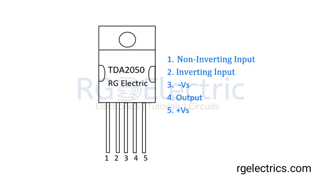
- Non-Inverting Input (Pin 1): The positive input terminal where the audio signal is applied.
- Inverting Input (Pin 2): The negative input terminal used for feedback connections.
- -Vs (Pin 3): The negative power supply pin, connected to the negative voltage rail.
- Output (Pin 4): The amplified output signal is available at this pin.
- +Vs (Pin 5): The positive power supply pin, connected to the positive voltage rail.
Features of TDA2050:
- High Output Power: The TDA2050 can deliver up to 32W of output power into a 4Ω load with low distortion, making it ideal for driving speakers.
- Low Harmonic and Crossover Distortion: The IC is designed for high-quality sound, minimizing harmonic and crossover distortion to ensure clear and accurate audio reproduction.
- Wide Supply Voltage Range: It operates on a wide supply voltage range, typically from ±4.5V to ±25V, making it versatile for different power supply configurations.
- High Output Current: The TDA2050 can deliver peak output currents up to 5A, ensuring robust performance even at higher volumes.
- Thermal Shutdown Protection: It includes built-in thermal protection to prevent damage from overheating, making it reliable in prolonged usage or high-demand conditions.
- Short-Circuit Protection: The IC has internal circuitry to protect against output short circuits, ensuring safe operation even in fault conditions.
- High Efficiency: Operating in class AB mode, it provides a good balance between efficiency and sound quality.
Circuit Diagram:
Working Explaination:
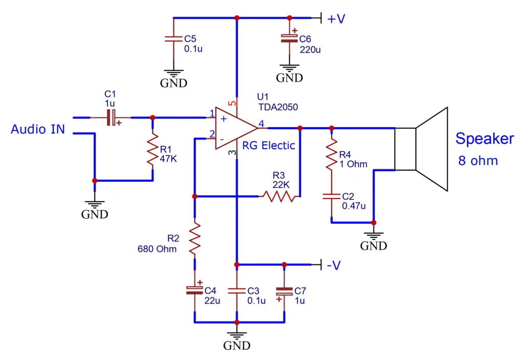
This TDA2050 amplifier circuit is designed to amplify an audio signal and deliver it to an 8-ohm speaker with low distortion and high efficiency. The input audio signal is fed through C1 (1uF), which acts as a coupling capacitor to block any DC component, ensuring that only the AC signal (audio) passes through. R1 (47kΩ) is used to set the input impedance, providing a stable load to the audio source.
The TDA2050 IC operates as the main amplifier. It has a non-inverting input at pin 1, while pin 2 serves as the inverting input. The gain of the amplifier is set by the feedback network, which consists of R3 (22kΩ) and R2 (680Ω). These resistors determine how much of the output signal is fed back to the inverting input to control the amplification level. This feedback stabilizes the gain and ensures consistent amplification.
To maintain stability and prevent oscillations, power supply bypass capacitors C5 (0.1uF) and C6 (220uF) are placed between the power supply rails (+V) and ground. Similarly, capacitors C3 (0.1uF), C4 (22uF), and C7 (1uF) decouple the negative power supply (-V), ensuring that any high-frequency noise or fluctuations are filtered out, providing a clean and stable supply voltage to the IC.
The output from pin 4 of the TDA2050 is sent to the speaker, and a Zobel network consisting of R4 (1Ω) and C2 (0.47uF) is placed across the output to ensure stability at higher frequencies. This network helps prevent high-frequency oscillations that could damage the amplifier or speaker.
In summary, this circuit efficiently amplifies an audio signal, providing clean and powerful output to drive an 8-ohm speaker, while incorporating various components to ensure stability, noise reduction, and protection of the IC and speaker.
Applications:
The TDA2050 amplifier is commonly used in various audio applications, including:
- Home audio systems – For driving bookshelf or floor-standing speakers.
- Car audio amplifiers – In-car stereo systems for better sound quality.
- Portable speaker systems – Battery-powered or AC-powered portable speakers.
- DIY audio projects – Used by hobbyists and engineers for small audio amplifiers.
- TV and multimedia speakers – For amplifying sound in televisions, computer speakers, or multimedia setups.
It is favored for its efficiency, high power output, and low distortion characteristics.


How to add volumen pot?
Audio IN → Potentiometer outer pin
Pot wiper → Junction of C1 (1uF)
Other pot outer pin → Ground
Schematic with potentiometer: https://rgelectrics.com/wp-content/uploads/2024/10/TDA2050-audio-amplifier-circuit-jpg.webp