Table of Contents
Introduction:
The Heart Beating Effect LED circuit is a simple yet visually captivating project often used in electronics to create a pulsing LED pattern that mimics the rhythm of a heartbeat. Using a 555 timer IC configured in astable mode, this circuit generates a continuous square wave that controls the blinking rate of the LEDs, giving them a pulsating effect. The circuit’s LEDs are arranged in a pattern resembling a heart shape, making it ideal for decorative purposes or as a beginner-friendly electronics project.
The 555 timer, in combination with a transistor, resistors, capacitors, and a diode, forms the core of this design. The timer’s oscillating output controls the transistor, which switches the LEDs on and off in a rhythmic sequence. Adjusting the values of specific resistors and capacitors allows users to modify the pulse rate, creating a customizable heartbeat effect. This circuit provides a hands-on approach to understanding the operation of the 555 timer and basic electronic components, making it popular among hobbyists and electronics enthusiasts.

Componenet details:
| S.no | Components | Value | Qty. |
|---|---|---|---|
| 1. | Time IC | NE555 | 1 |
| 2. | Resistor | 120K, 10K | 2, 2 |
| 3. | Capacitor | 100uf, 10uf | 1, 1 |
| 4. | Diode | 1N4007 | 1 |
| 5. | Transistor | BD136 | 1 |
| 6. | LED | RED | 24 |
| 7. | Battery | 4V | 1 |
NE555 Pinout:

The NE555 timer IC is an 8-pin chip commonly used for generating precise timing and oscillation in circuits. Here’s a description of the pinout:
- GND (Pin 1): Ground, connected to the negative side of the power supply.
- VCC (Pin 8): Supply voltage, connected to the positive side of the power supply. It typically ranges from 4.5V to 15V, depending on the application.
- DIS (Pin 7): Discharge pin. It’s connected to the timing capacitor, and discharges it when the output is low (used in astable and monostable modes).
- OUT (Pin 3): Output pin. Provides the output signal (either high or low) depending on the timer’s state.
- RST (Pin 4): Reset pin. If pulled low, it resets the timer and forces the output low. Usually tied to VCC when not used.
- THRS (Pin 6): Threshold pin. It compares the voltage of the capacitor with 2/3 of VCC. If the threshold exceeds this value, the output switches.
- TRIG (Pin 2): Trigger pin. A low voltage (<1/3 of VCC) on this pin causes the output to go high. Used to start the timing cycle.
- CV (Pin 5): Control voltage. Allows external adjustment of the internal reference voltage (usually connected to ground via a capacitor for stability).
Circuit Diagram:

Working Explaination:
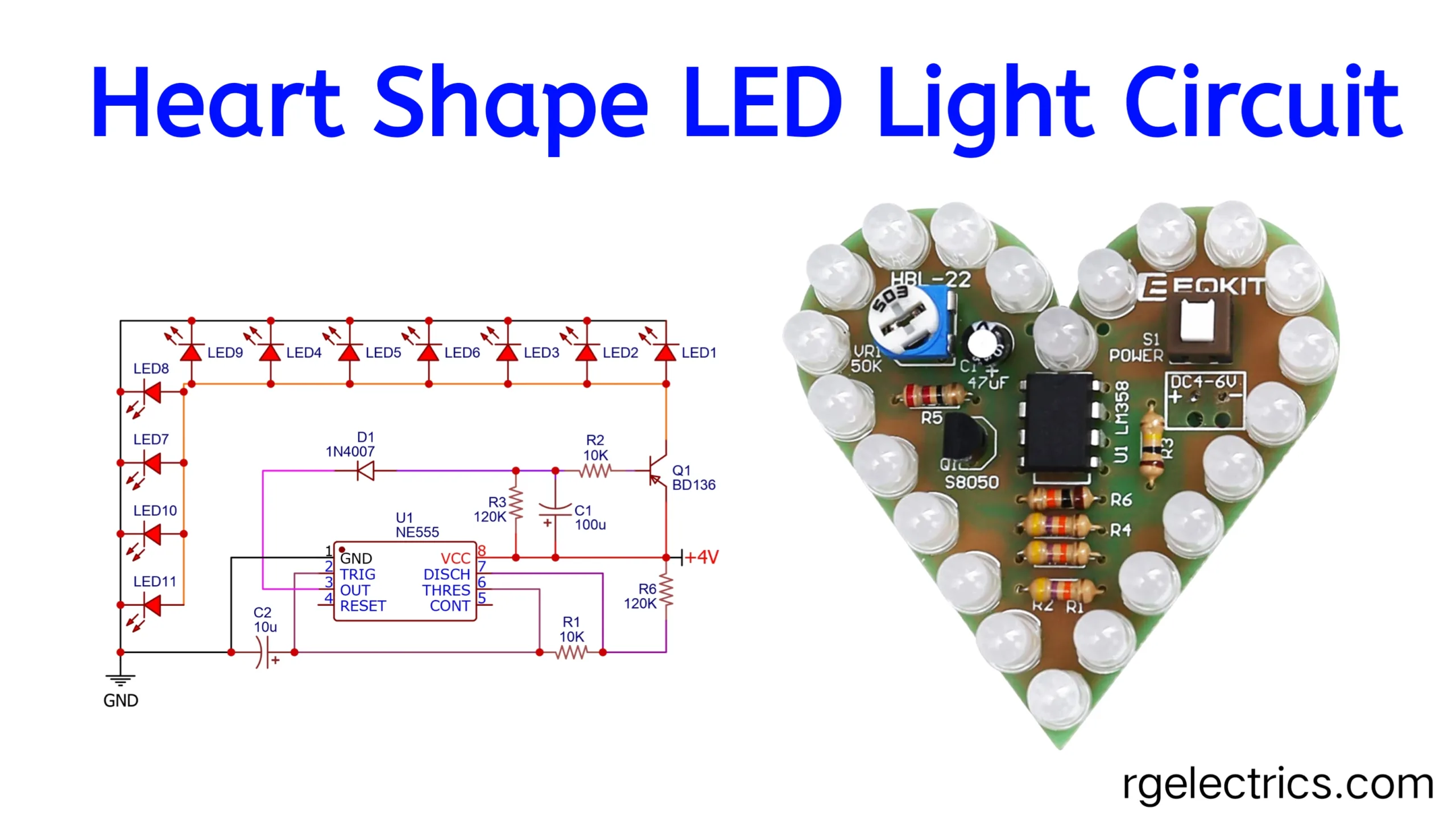
This heart-beating LED circuit uses a 555 timer IC configured in astable mode to produce a pulsing effect on a series of LEDs. The 555 timer generates a square wave output on pin 3, with its frequency determined by resistors ( R1 ), ( R6 ), and capacitor ( C2 ), setting the rate of the LED “heartbeat.” When the timer output is high, the signal passes through resistor ( R2 ) to the base of transistor ( Q1 ) (BD136), which switches on, allowing current to flow through the LEDs. These LEDs, arranged to resemble a heart shape, light up in a pulsating manner as ( Q1 ) alternates between on and off states. Capacitor ( C1 ) stabilizes the pulse duration, while diode ( D1 ) (1N4007) protects the circuit from any reverse current.
The pulsing speed of the LEDs can be adjusted by changing the values of ( R1 ), ( R6 ), or ( C2 ), controlling the frequency of the 555 timer. Powered by a 4V DC source, this simple circuit effectively simulates a heartbeat, making it ideal as a decorative project or for learning basic electronics principles.
Applications and Uses:
This heart-beating LED circuit has a variety of applications:
- Decorative Lighting: The pulsating effect mimics a heartbeat, making it ideal for decorations, such as Valentine’s Day ornaments, party decor, or festive lighting.
- Educational Projects: This circuit is simple enough for beginners, making it a popular project for students and hobbyists to learn about the 555 timer IC, transistors, and basic circuit design.
- Medical-Themed Displays: It can be used in medical-themed art or educational displays to represent heartbeats, helping to visually illustrate heart rate concepts.
- Toys and Crafts: The beating light effect can enhance handmade toys or crafts, adding a dynamic, engaging feature to DIY projects.

