
Table of Contents
Introduction:
A wireless power transmission circuit is designed to transfer electrical energy from a power source to a load without using physical wires. The basic principle behind wireless power transfer is electromagnetic induction or resonant inductive coupling. The BC547 wireless power transmission circuit utilizes the BC547 transistor as a switching element to create an efficient system for transferring electrical energy without physical connections. This circuit operates on the principle of electromagnetic induction, where a transmitter coil generates an oscillating magnetic field when an alternating current flows through it.
Components Required:
| S.No | Components | Value | Qty. |
|---|---|---|---|
| 1. | Transistor – NPN | BC547 | 1 |
| 2. | Resistor | 1K | 1 |
| 3. | Insulated Copper Wire | 0.25mm | – |
| 4. | Battery | 3.7V | |
| 5. | LED | – | – |
BC547 Pinout:
The BC547 is a widely used NPN bipolar junction transistor (BJT). It is commonly employed in low-power switching and amplification applications. Here’s a breakdown of its characteristics:

- Collector (C): This is the terminal where the output current flows out of the transistor.
- Base (B): The base terminal controls the transistor’s operation. A small current at this terminal allows a larger current to flow between the collector and emitter.
- Emitter (E): The emitter is the terminal from which the current leaves the transistor.
Key Specifications:
- Type: NPN transistor
- Maximum Collector-Emitter Voltage (Vce): 45V
- Maximum Collector Current (Ic): 100mA
- Power Dissipation (Ptot): 500mW (maximum)
- DC Current Gain (hFE): 110 to 800 (varies by model and conditions)
- Transition Frequency (fT): 300 MHz (typical)
- Pin Configuration:
- Pin 1: Collector
- Pin 2: Base
- Pin 3: Emitter
Applications:
- Switching: It is often used in circuits to switch low-power devices like LEDs, relays, and other components.
- Amplification: The BC547 can amplify small current signals, making it suitable for audio amplifiers, signal amplifiers, and other similar applications.
- Oscillators and Signal Processing: It is used in circuits that generate or process AC signals.
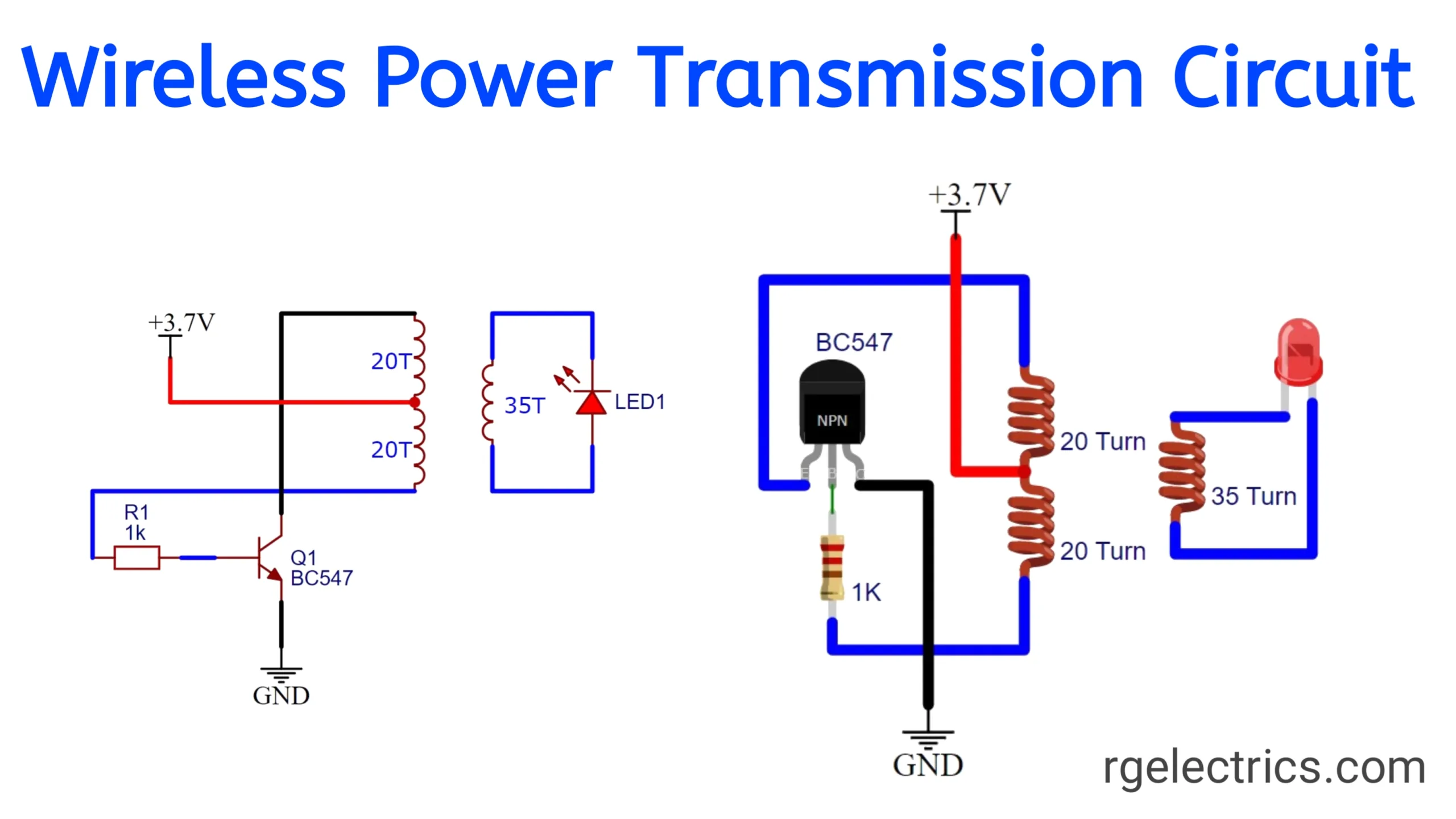
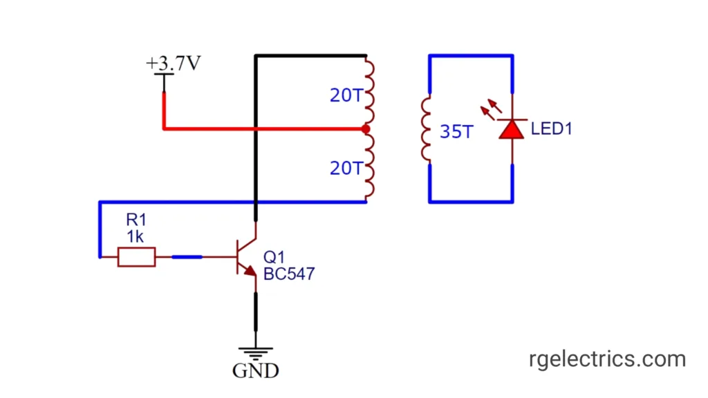
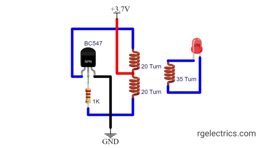
Circuit Diagram:
Working Explaination:
key components and their roles in this circuit:
- Power Source (+3.7V): This provides the necessary power for the circuit. A 3.7V battery (likely a Li-ion cell) is used.
- BC547 Transistor (Q1): This NPN transistor acts as a switch and oscillator in this circuit. It is used to control the flow of current and generate the necessary frequency for wireless transmission.
- R1 (1kΩ Resistor): This resistor limits the current to the base of the BC547 transistor, preventing it from being damaged.
- Coil (20T+20T, 35T):
- Primary Windings. In the transmitter circuit, the primary windings are 20-0-20 turns with a diameter of 4 cm using 0.25mm insulated copper wire.
- Secondary Winding. In the receiver circuit, the secondary winding is 35 turns with a diameter of 4 cm using 0.25mm insulated copper wire.
- LED (LED1): The LED in the receiving section lights up when power is successfully transmitted wirelessly from the transmitter coil to the receiver coil.
How It Works:
- The transistor Q1, along with the inductor coils, forms a basic oscillator circuit. The 20T coils in the transmitter generate an alternating magnetic field when the transistor oscillates.
- This alternating field induces a current in the 35T coil in the receiver circuit, lighting up the LED (LED1).
- The wireless power transmission happens via electromagnetic induction between the transmitter and receiver coils.
This type of circuit is often used for small-scale experiments in wireless power transfer, where a low-power LED or other devices are powered wirelessly over a short distance.
Applications:
- Wireless LED Lighting: A simple use case of this circuit is to power an LED wirelessly, making it ideal for experimenting with wireless lighting systems or wireless signaling.
- Educational and Demonstration Purposes: It is commonly used in educational settings to demonstrate the principles of electromagnetic induction and wireless power transmission in a simple, hands-on way.


