

Table of Contents
Introduction:
The TDA7377 is a versatile, high-performance, class AB audio amplifier integrated circuit (IC) that is widely used in car audio systems, home audio systems, and other stereo audio amplification applications. Manufactured by STMicroelectronics, the TDA7377 is designed to amplify low-level audio signals to a level that can drive loudspeakers directly. It is capable of delivering 2x30W or 4x6W power output depending on the configuration, making it suitable for stereo or quadraphonic (four-channel) sound systems.
The TDA7377 is a widely-used, high-performance, and compact audio amplifier IC designed for low-distortion sound amplification. With integrated protection features, its versatility and reliability make it ideal for automotive, home audio systems, and various portable speaker applications.
Component Details:
| S.No | Components | Value | Qty. |
|---|---|---|---|
| 1. | IC | TDA7377 | 1 |
| 2. | Capacitor | 1000uf, 47uf, 10uf, 100nf, 0.47uf | 1,1,1,2,1 |
| 3. | Resistor | 10KΩ | 1 |
| 4. | Speaker | 4Ω | 2 |
| 5. | Audio Input | – | – |
| 6. | Power Supply | 12V | – |
TDA7377 Pinout:
The TDA7377 is a class AB power amplifier capable of delivering high-quality stereo audio output. It is designed to drive two speakers in stereo mode or four speakers in a bridge-tied load (BTL) configuration. It operates with a supply voltage range of 8V to 18V, which makes it suitable for use in automotive and home audio applications.
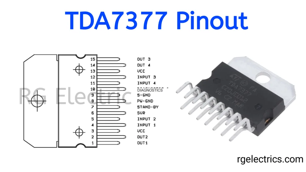
- Pin 1 (OUT1): Output for channel 1 (typically used in a stereo or bridge-tied configuration).
- Pin 2 (OUT2): Output for channel 2.
- Pin 3 (VCC): Positive supply voltage input. This is where you connect the power supply (8V to 18V).
- Pin 4 (INPUT1): Input for audio signal 1.
- Pin 5 (INPUT2): Input for audio signal 2.
- Pin 6 (SUR): Possibly used for internal connections in specific configurations (not typically used in simpler stereo applications).
- Pin 7 (STAND-BY): Standby control pin. Used to enable or disable the amplifier’s functionality.
- Pin 8 (PW-GND): Power ground. Connects to the ground or negative side of the power supply.
- Pin 9 (S-GND): Signal ground. Used as a ground reference for the audio signal.
- Pin 10 (DIAGNOSTICS): This pin is used for fault detection or diagnostics (e.g., to detect short circuits or thermal issues).
- Pin 11 (INPUT4): Input for audio signal 4.
- Pin 12 (INPUT3): Input for audio signal 3.
- Pin 13 (VCC): Another pin for the power supply, connected to the positive voltage (parallel to Pin 3).
- Pin 14 (OUT4): Output for channel 4.
- Pin 15 (OUT3): Output for channel 3.
Key Features of the TDA7377:
- High Output Power: It can deliver up to 30W per channel in stereo mode or 6W per channel in a four-channel configuration.
- Versatile Configuration: The IC supports both stereo (2-channel) and quad (4-channel) configurations, providing flexibility depending on the audio system design.
- Wide Supply Voltage Range: Operates from a power supply of 8V to 18V, which is particularly useful for automotive audio systems where the available voltage may vary.
- Low Distortion: Class AB operation ensures low harmonic distortion and high-fidelity sound reproduction, maintaining audio quality at high volumes.
- Overheat and Short Circuit Protection: The IC includes built-in thermal shutdown and short-circuit protection features to prevent damage during overload conditions.
- Standby and Mute Control: The TDA7377 has standby and mute modes, which help save power and reduce noise during operation.
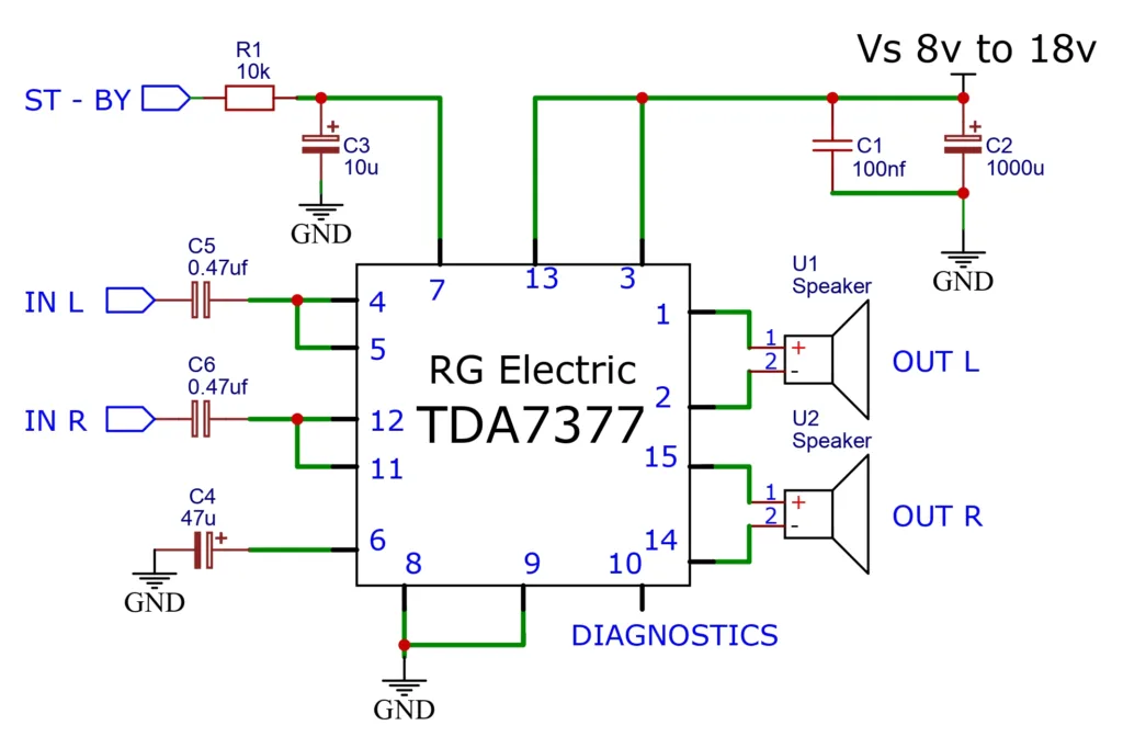
Circuit Diagram:
Working Explaination:
Pin Configuration of TDA7377
- Pin 1 and Pin 2: These are the outputs for the left (OUT L) and right (OUT R) audio channels, connected to speakers U1 and U2. Each speaker has a positive (+) and a negative (-) terminal.
- Pin 3 (Vs): Power supply pin. The supply voltage for the circuit ranges from 8V to 18V. Capacitors C1 (100nF) and C2 (1000uF) are used for power supply decoupling to smooth out any voltage spikes or fluctuations and reduce noise.
- Pin 4 (IN L): This is the left audio input, coupled with a 0.47µF capacitor (C5) to block DC signals and allow AC audio signals to pass through.
- Pin 5 (IN R): This is the right audio input, also coupled with a 0.47µF capacitor (C6) for the same purpose as C5.
- Pin 6 (GND): Ground connection for the circuit, providing the necessary return path for current.
- Pin 7 (ST-BY): Standby control pin, which is used to enable or disable the amplifier. A 10kΩ resistor (R1) and a 10µF capacitor (C3) are connected to this pin to provide a delay for stable operation during power-up.
- Pin 8 and Pin 9 (GND): Additional ground pins to ensure the proper grounding of the IC for better stability and noise reduction.
- Pin 10 (DIAGNOSTICS): This pin can be used for fault diagnostics (not connected in this circuit).
- Pins 11 and 12: Not connected in this particular circuit configuration.
- Pin 14 and Pin 15: These are also connected to the outputs (OUT R and OUT L) for the right and left audio channels, tied to the speakers.
Explanation of Components
- C1 (100nF) and C2 (1000µF): These capacitors are connected to the power supply. C1 is used for high-frequency noise filtering, and C2 provides bulk decoupling to smooth the supply voltage.
- C3 (10µF): Connected to the standby pin, this capacitor helps in controlling the standby function, ensuring the amplifier powers up smoothly without sudden noise.
- C4 (47µF): This is a decoupling capacitor for the internal circuits of the amplifier.
- C5 and C6 (0.47µF): These capacitors are used to couple the left (IN L) and right (IN R) audio inputs to the amplifier, ensuring only AC signals (audio signals) pass through.
- R1 (10kΩ): A pull-up resistor used with the standby function to control the amplifier’s power state.
Working Principle
- Audio Input: The audio signals (IN L and IN R) are fed into the amplifier through coupling capacitors C5 and C6, which block DC components and allow only the AC audio signal to pass through.
- Amplification: The TDA7377 amplifies these input signals based on the internal circuitry of the IC, powered by the supply voltage (Vs).
- Audio Output: The amplified audio signals are sent to the speakers connected to the output pins (OUT L and OUT R). The speaker output provides sufficient power to drive standard audio speakers.
- Standby Function: The standby pin (ST-BY) is used to control whether the amplifier is active. When the voltage on this pin is high, the amplifier is in standby mode and consumes minimal power.
Power Supply
The circuit is powered by a DC supply of 8V to 18V, which makes it suitable for automotive applications where 12V power is common. The capacitors C1 and C2 filter the supply voltage to ensure stable operation of the amplifier and reduce noise in the audio output.
Speakers
The speakers connected to OUT L and OUT R should be of an appropriate impedance (typically 4Ω or 8Ω). They will receive the amplified audio signal from the IC, producing stereo sound.
Conclusion
This circuit is a basic stereo audio amplifier designed using the TDA7377 IC. It is simple to build and can be used in various audio applications such as car stereo systems and small home audio systems. The circuit provides sufficient power output for two-channel stereo systems and includes features such as standby control for power management.
Applications:
The TDA7377 is typically used in audio amplification systems such as:
- Car Audio Systems: Due to its high power output, wide voltage range, and reliability, the TDA7377 is widely used in car amplifiers, delivering clear and powerful sound to in-car speakers.
- Home Audio Systems: It can be used in DIY stereo systems, multimedia speaker systems, or as part of larger home theater systems.
- Portable Speaker Systems: Its compact design and low power consumption make it ideal for battery-operated or portable audio amplifiers.
- Public Address (PA) Systems: It can drive loudspeakers in PA systems, ensuring clear and loud sound output for announcements or music.


