Table of Contents
TDA7052 1W Mono Audio Amplifier Circuit
Introduction:
The TDA7052 audio amplifier circuit is a compact and efficient design for amplifying low-power audio signals, typically used in battery-operated or portable devices. The TDA7052 is a 1-watt mono audio amplifier integrated circuit (IC) designed to operate on low supply voltages, ranging from 3V to 6V. It offers excellent performance in amplifying audio signals for small speaker applications such as in toys, handheld devices, and portable audio systems.
The circuit utilizes minimal external components, including a few capacitors and a potentiometer for volume control, making it ideal for simple and low-cost audio amplification projects. Its built-in features, such as thermal shutdown and low distortion, provide reliable and clear sound output when connected to an 8-ohm speaker. Overall, this amplifier is well-suited for small, power-efficient applications requiring basic audio amplification.
Components Required:
| S.no | Components | Value | Qty. |
|---|---|---|---|
| 1. | IC | TDA7052 | 1 |
| 2. | Capacitor | 100uf, 0.1uf | 1, 2 |
| 3. | Variable Resistor | 5K | 1 |
| 4. | Speaker | 8 ohm | 1 |
| 5. | Audio Input | – | – |
| 6. | Power Supply | 6V | – |
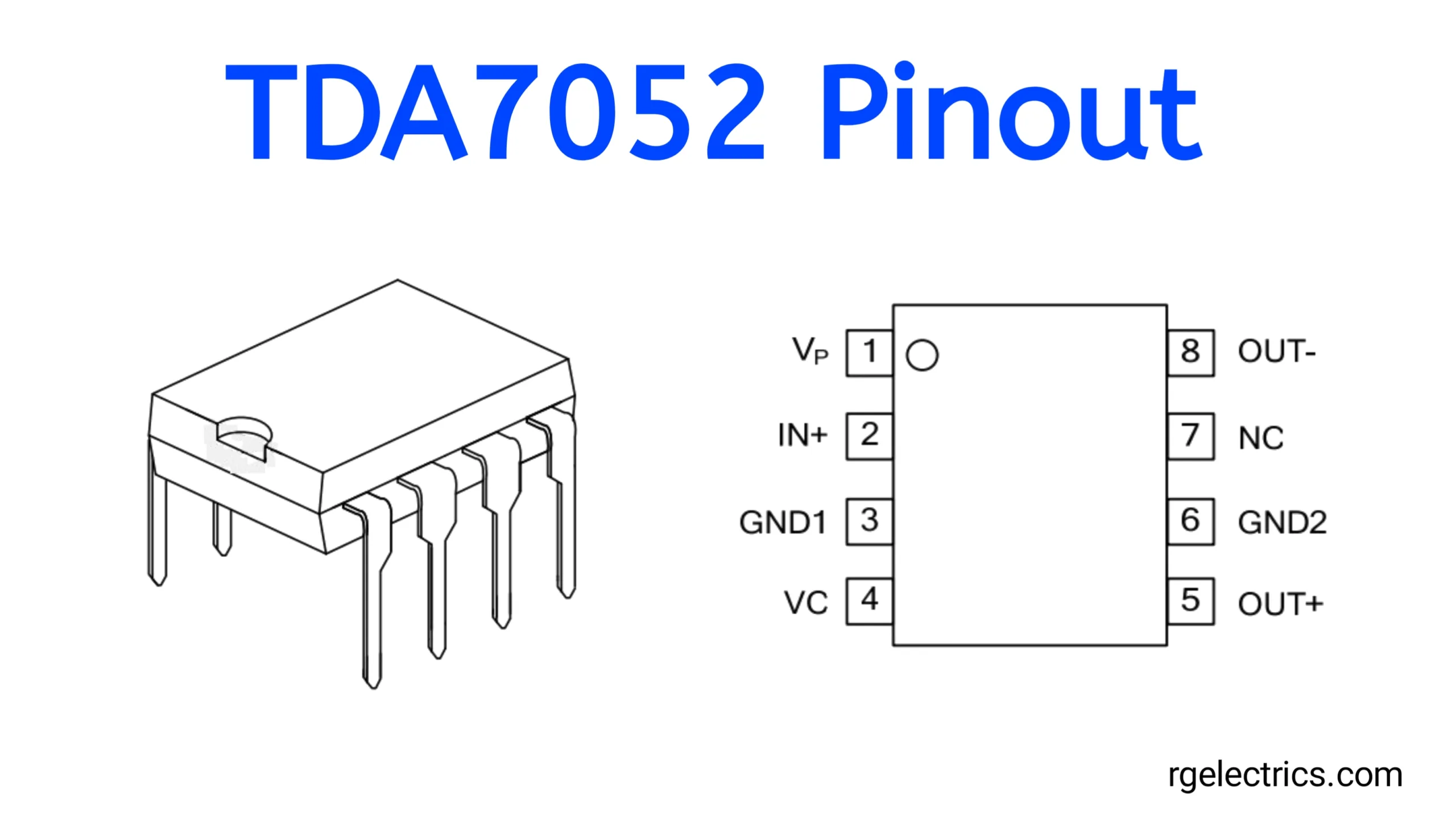
TDA7052 Pinout:

Pin Descriptions:
- Pin 1 (VP): Supply Voltage Positive (Power Supply Pin)
- Connect the positive terminal of the power supply (3V to 6V) here.
- Pin 2 (IN+): Non-Inverting Input
- This is the input pin for the audio signal. The signal is applied here for amplification.
- Pin 3 (GND1): Ground
- This is the ground pin for the input section of the IC. It connects to the system ground.
- Pin 4 (VC): Volume Control (optional)
- This pin can be used for volume control. In some designs, it is connected to an external potentiometer or other volume adjustment circuitry.
- Pin 5 (OUT+): Positive Output
- This is one of the audio output pins. It connects to the positive terminal of the speaker.
- Pin 6 (GND2): Ground
- This is the ground pin for the output section. It should be connected to the system ground.
- Pin 7 (NC): No Connection
- This pin is not connected internally. It can be left unconnected in the circuit.
- Pin 8 (OUT-): Negative Output
- This is the second output pin, connecting to the negative terminal of the speaker.
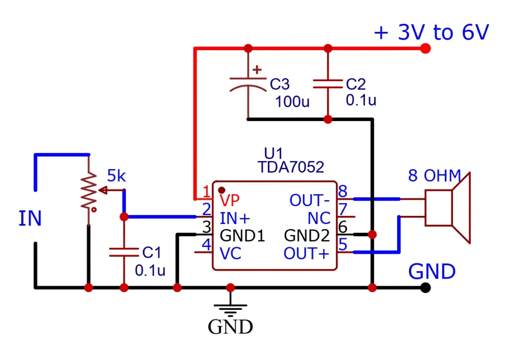
Circuit Diagram:

Circuit Working:
1. Power Supply:
- The circuit requires a DC power supply in the range of 3V to 6V. This voltage powers the TDA7052 IC through pin 1 (VP). The capacitors C2 (0.1µF) and C3 (100µF) help smooth out any voltage ripples or noise from the power supply to provide stable power to the IC.
2. Audio Input:
- The input audio signal (e.g., from a microphone or audio device) is fed to the IN terminal of the circuit. The signal passes through a 5kΩ potentiometer. This potentiometer acts as a volume control. By adjusting the resistance, you change the amplitude of the input signal.
- After the potentiometer, the signal passes through C1 (0.1µF), a coupling capacitor, which blocks any DC component from the input signal while allowing the AC audio signal to pass through.
- The audio signal is then applied to pin 2 (IN+) of the TDA7052.
3. Amplification:
- The TDA7052 is an audio amplifier IC, designed to boost the audio signal. It amplifies the input signal applied at pin 2 (IN+), using the voltage provided at pin 1 (VP).
- Internally, the IC uses a feedback network to ensure stability and proper amplification. This IC has a fixed gain, so the amplification is determined by the design of the chip, making it easy to use without the need for external components to set gain.
4. Audio Output:
- The amplified output signal is available at pin 5 (OUT+) and pin 8 (OUT-). These pins are connected to an 8-ohm speaker, with the positive side of the speaker connected to OUT+ and the negative side to OUT-.
- The IC outputs a differential signal, meaning that it delivers both positive and negative swings, resulting in a higher effective output power to the speaker. This makes the amplifier more efficient, especially for low-voltage operations.
5. Grounding:
- The circuit has multiple ground connections: pin 3 (GND1) and pin 7 (GND2) are internally connected inside the IC and are connected to the system ground. Additionally, the negative terminal of the power supply and the ground side of the input signal also connect to the system ground.
6. Volume Control:
- The 5kΩ potentiometer acts as a volume control. By varying the resistance, you adjust the level of the input signal, which in turn changes the volume level at the output. When the potentiometer resistance is low, more signal is allowed through, resulting in a louder output. When the resistance is high, the input signal is attenuated, resulting in a lower output volume.
7. Speaker Output:
- The speaker connected to the output terminals (pins 5 and 8) converts the amplified electrical signal into sound. The differential output helps maximize the efficiency of the amplifier, making it suitable for driving small speakers directly.
Overall Operation:
When a small input audio signal is fed into the IN terminal, it is first attenuated or amplified by the potentiometer. The signal is then coupled to the amplifier input, where the TDA7052 IC amplifies it and sends the stronger signal to the connected speaker. The speaker produces sound corresponding to the amplified audio signal.
Features of the Circuit:
- Low Voltage Operation: Works between 3V to 6V, making it suitable for battery-powered applications.
- Built-in Gain: The TDA7052 has an internal gain, so no external gain-setting resistors are required.
- Differential Output: Provides higher power output without needing large supply voltages.
- Compact and Simple: The design is minimal, with only a few passive components, making it easy to build and cost-effective.
This amplifier is commonly used in small audio devices such as radios, portable speakers, or toys.
Appliactions & Uses:
- Portable speakers
- Battery-powered radios
- Toys with sound output
- Small audio amplifiers in gadgets


