Table of Contents
Introduction:
An LED flashing circuit is a simple yet effective way to demonstrate the use of the NE555 timer integrated circuit (IC) in astable mode, where it generates continuous pulses. This circuit is widely used in hobby electronics, signaling applications, and as a fundamental introduction to timer ICs. The primary function of the circuit is to turn an LED on and off at regular intervals, creating a blinking or flashing effect.
The NE555 timer, a versatile and widely used IC, is the core of this circuit. It can be configured in different modes, and in this case, it is set to astable mode, meaning it operates without any stable state—continuously switching between high and low output. By using basic electronic components like resistors, capacitors, and LEDs, this circuit allows for easy control of the LED’s flashing rate through the manipulation of resistance and capacitance values.
This simple yet instructive circuit introduces basic timing concepts and is often the foundation for more advanced timing or pulse generation projects.

Component Details:
| S.No | Components | Value | Qty. |
|---|---|---|---|
| 1. | Time IC | NE555 | 1 |
| 2. | Capacitor | 10uf | 1 |
| 3. | Resistor | 1k, 100k | 1,1 |
| 4. | LED | – | 1 |
| 5. | Battery | 3.7V | 1 |
NE555 Pinout:

Circuit Diagram:

Circuit Explaination:
Components:
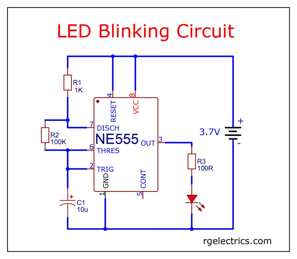
- NE555 Timer IC: This is the main component, configured in astable mode, where it continuously switches between high and low states, creating a square wave.
- Resistors (R1, R2): R1 (1KΩ) and R2 (100KΩ) set the timing intervals for the LED flashes.
- Capacitor (C1): This 10μF capacitor helps determine the frequency of the LED flashing, working together with R1 and R2.
- LED: The light-emitting diode flashes on and off based on the NE555’s output.
- Resistor (R3): A current-limiting resistor (100Ω) protects the LED.
- Power Source: A 3.7V power supply, commonly a Li-ion battery, powers the circuit.
How it works:
- When power is applied, the NE555 timer continuously charges and discharges the capacitor (C1) through resistors R1 and R2.
- This oscillation between charging and discharging causes the output at pin 3 to switch between high and low.
- When pin 3 is high, the LED turns on, and when pin 3 is low, the LED turns off, causing it to flash at a regular interval.
This is a simple LED flasher circuit often used in hobby electronics.
Uses of LED Flashing Circuit:
An LED flashing circuit has various practical applications, both in educational projects and real-world applications. Some of the most common uses include:
- Visual Indicators
- Signaling and Alert Systems
- Decorative Lighting
- Educational Purposes


