Table of Contents
Introduction
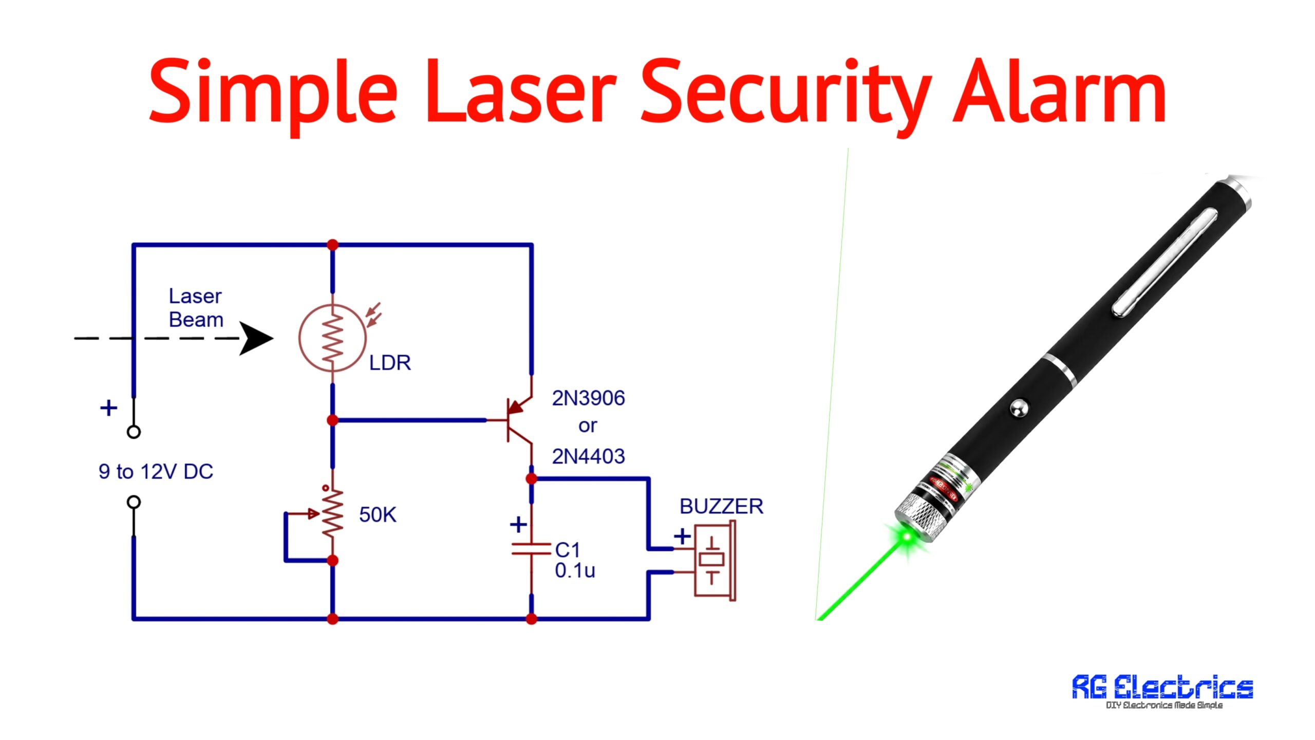
A Simple Laser Security Alarm Circuit is an easy electronics project that can detect when a laser beam falling on an LDR is interrupted. The circuit uses an LDR (Light Dependent Resistor), a 50K preset, and a PNP transistor (2N3906 or 2N4403) to control a buzzer.
The basic idea is very simple: a laser beam is continuously directed at the LDR. When the beam reaches the LDR, the transistor remains OFF and the buzzer stays silent. If someone crosses the laser beam, the light falling on the LDR is interrupted. This changes the LDR resistance and switches the transistor ON, activating the buzzer.
Components Required
| S.No. | Component Name | Value / Type | Qty. |
|---|---|---|---|
| 1 | LDR | Light Dependent Resistor | 1 |
| 2 | Preset | 50KΩ | 1 |
| 3 | PNP Transistor | 2N3906 / 2N4403 | 1 |
| 4 | Capacitor | 0.1µF | 1 |
| 5 | Buzzer | DC Buzzer | 1 |
| 6 | Laser Module | Red/visible laser | 1 |
| 7 | DC Power Supply | 9–12V DC | 1 |
| 8 | Connecting Wires | — | As required |
Note: Make sure the buzzer is rated for the supply voltage you use. Also, never point a laser at people's eyes, vehicles, or aircraft.
Pinout
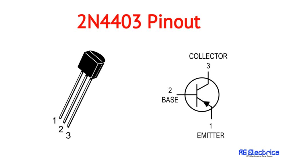
2N3906 / 2N4403 PNP Transistor
The transistor is used as an electronic switch.
| Pin | Function |
|---|---|
| 1. | Emitter |
| 2. | Base |
| 3. | Collector |
Circuit Diagram
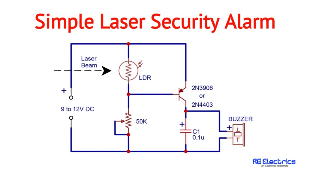
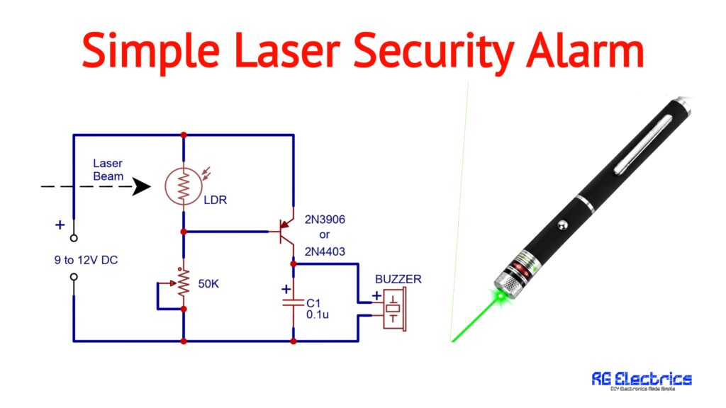
The circuit consists of an LDR and a 50K preset forming the sensing network. The sensing voltage is applied to the base of the PNP transistor. The transistor then controls the buzzer.
The LDR is connected between the positive supply and the transistor base, while the 50K preset is connected between the base and ground.
The capacitor C1 (0.1µF) is connected across the transistor’s output and ground.
Working Principle
The circuit works by detecting a change in light intensity on the LDR.
An LDR has low resistance when exposed to light and its resistance increases when the light level decreases.
1. Laser Beam Present
When the laser beam is continuously focused on the LDR, the LDR resistance becomes relatively low.
This keeps the transistor’s base at a voltage that keeps the PNP transistor OFF.
As a result:
Laser ON → LDR illuminated → Transistor OFF → Buzzer OFF
So, under normal conditions, the alarm remains silent.
2. Laser Beam Interrupted
When a person or object crosses the laser beam, the laser light no longer reaches the LDR.
The resistance of the LDR increases considerably. This changes the voltage at the transistor’s base.
The base is pulled toward the negative supply through the 50K preset, causing the PNP transistor to turn ON.
The transistor then supplies power to the buzzer.
The sequence becomes:
Laser beam blocked → LDR resistance increases → Transistor ON → Buzzer ON
Therefore, the buzzer alerts you whenever the laser beam is interrupted.
Role of the 50K Preset
The 50K preset is used to adjust the sensitivity of the alarm.
Different LDRs, laser modules, room lighting conditions, and distances can produce different resistance values. The preset allows you to adjust the switching point of the transistor.
To set the circuit:
- Power the circuit with the laser beam falling directly on the LDR.
- Adjust the 50K preset until the buzzer remains OFF.
- Block the laser beam.
- Check that the buzzer turns ON.
- Fine-tune the preset if necessary.
This adjustment is particularly useful when there is unwanted ambient light around the LDR.
Role of C1 0.1µF Capacitor
The 0.1µF capacitor (C1) is connected at the transistor output.
It can help suppress small unwanted voltage fluctuations and electrical noise in the switching circuit. This can make the alarm operation more stable.
However, this simple circuit does not use C1 as a timing capacitor for generating the buzzer sound. The buzzer itself produces the audible sound.
How to Build the Circuit
Step 1: Connect the Power Supply
Connect the positive terminal of the 9–12V DC supply to the positive rail and the negative terminal to the ground rail.
Step 2: Connect the LDR
Connect one terminal of the LDR to the positive supply.
Connect its other terminal to the transistor’s base/sensing node.
Step 3: Connect the 50K Preset
Connect the preset between the sensing node and ground as shown in the circuit diagram.
The preset’s wiper is connected to the lower terminal so it functions as an adjustable resistance.
Step 4: Connect the PNP Transistor
Connect the emitter of the 2N3906 or 2N4403 to the positive supply.
Connect the base to the LDR/preset junction.
Connect the collector to the buzzer’s positive terminal.
Step 5: Connect the Buzzer
Connect the buzzer between the transistor collector and ground.
Step 6: Connect C1
Connect the 0.1µF capacitor between the transistor output/collector node and ground.
Step 7: Align the Laser
Place the laser module at a suitable distance and point it directly toward the LDR.
Adjust the position until the laser spot falls properly on the sensitive surface of the LDR.
Testing the Laser Security Alarm
After completing the circuit, turn ON the power supply and align the laser beam with the LDR.
If the circuit is adjusted correctly:
When the laser reaches the LDR:
➡️ Buzzer remains OFF.
When the laser is blocked:
➡️ Buzzer turns ON.
If the buzzer remains ON even when the laser is shining on the LDR, slowly adjust the 50K preset until the desired switching point is obtained.
Applications
This simple laser alarm can be used for:
- Door and entrance monitoring
- Room security experiments
- Cabinet or drawer protection
- School and college electronics projects
- DIY security systems
- Demonstrating LDR-based switching
- Laser beam interruption experiments
- Electronics science projects
Advantages
- Simple circuit: Only a few components are required.
- Low cost: Components are easily available.
- Adjustable: Sensitivity can be controlled with the 50K preset.
- Easy to assemble: Suitable for breadboard construction.
- No microcontroller required: The circuit works using a transistor switching arrangement.
- Fast response: Blocking the laser beam changes the LDR resistance immediately.
Limitations
This is a basic demonstration/security alarm circuit, not a professional security system. Strong ambient light, sunlight, reflections, LDR characteristics, and laser alignment can affect its operation.
For a more reliable installation, the LDR should be shielded from unwanted surrounding light while still allowing the laser beam to reach it.
Conclusion
The Simple Laser Security Alarm Circuit using LDR and 2N3906/2N4403 is an excellent beginner-friendly electronics project. It demonstrates how light can be converted into an electrical switching signal using an LDR and how a transistor can be used to control an alarm.
Under normal conditions, the laser keeps the LDR illuminated and the buzzer remains OFF. When the laser beam is interrupted, the LDR resistance changes, switching the PNP transistor ON and activating the buzzer. The 50K preset makes it possible to adjust the circuit according to the surrounding light conditions.