Table of Contents
Introduction
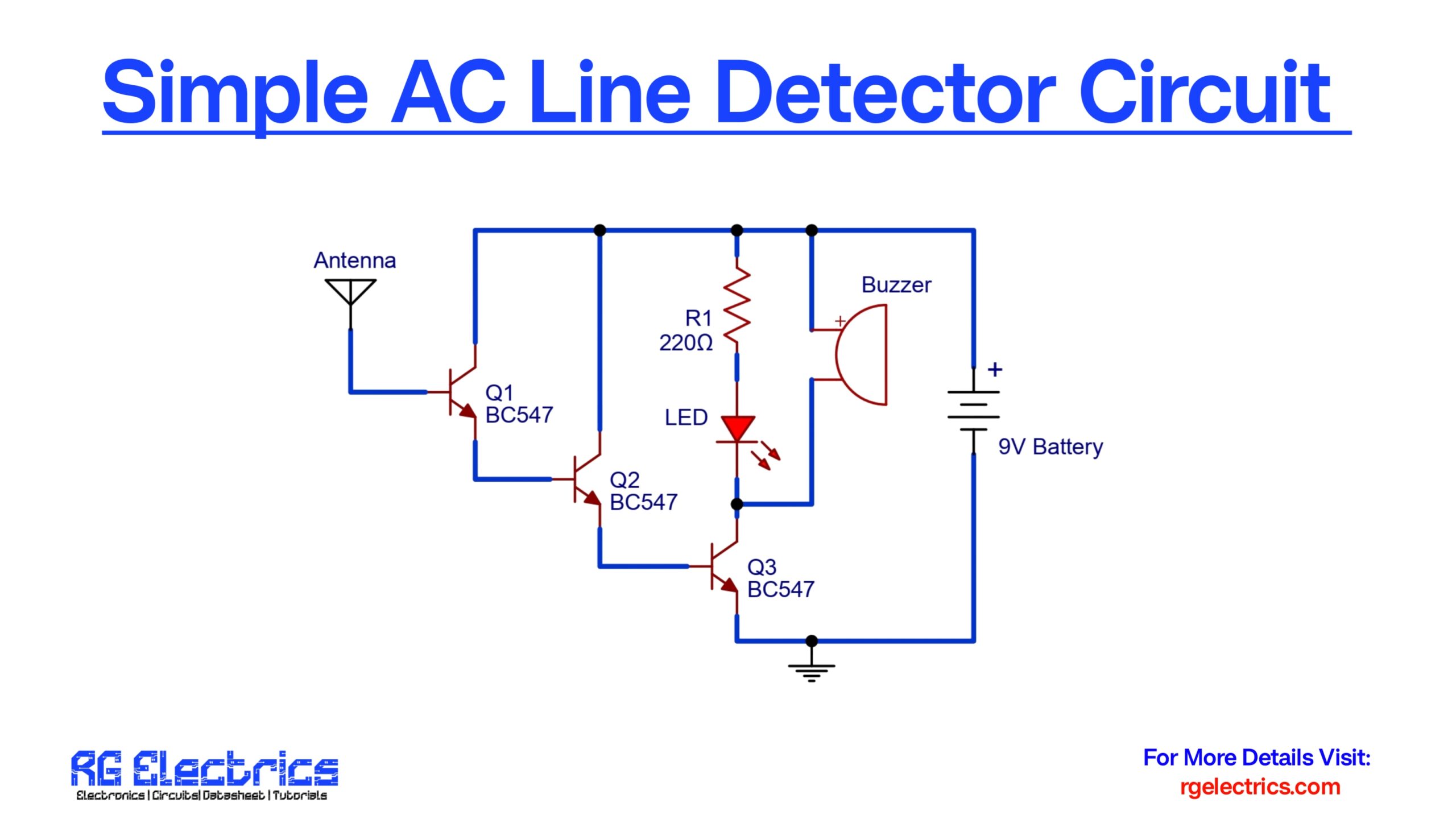
The AC line detector circuit is a handy non-contact voltage tester that helps detect the presence of alternating current (AC) in a wire or line without direct electrical contact. It is particularly useful for safely identifying live wires, checking for broken AC lines inside walls, or locating cable faults. This circuit works by sensing the electromagnetic field around AC lines using an antenna (a short piece of wire), which triggers a response from the components — turning ON a buzzer and an LED as indicators.
Unlike commercial testers that may be complex or expensive, this simple circuit is easy to build using readily available components and provides reliable results. It’s powered by a 9V battery, making it portable and safe to use in residential and field environments.
Components Details
| S.No | Component Name | Value/Specification | Quantity |
|---|---|---|---|
| 1 | Transistor | BC547 | 3 |
| 2 | Resistor | 220Ω (R1) | 1 |
| 3 | LED | Red or Green | 1 |
| 4 | Buzzer | 9V DC Buzzer | 1 |
| 5 | Antenna | Short Wire (5–10 cm) | 1 |
| 6 | Battery | 9V Battery | 1 |
| 7 | Connecting Wires | – | As needed |
Bc547 Pinout

Circuit Diagram

Circuit Explanation
The circuit employs three BC547 transistors (Q1, Q2, Q3) configured in a cascaded amplifier arrangement. Here’s a step-by-step explanation:
- Antenna Input: A short wire acts as an antenna and is responsible for picking up the electromagnetic field emitted by live AC wires nearby. This weak AC signal is enough to bias the base of Q1 (first transistor).
- Amplification Stage:
- When the antenna senses an AC field, Q1 gets slightly biased, allowing a small current to flow.
- This signal is amplified and fed into Q2, which further strengthens the signal and passes it to Q3.
- Each transistor stage multiplies the signal strength, effectively making the circuit highly sensitive.
- Output Indication:
- Once Q3 is fully turned ON, it completes the circuit for the LED and buzzer.
- The LED glows to provide a visual indication.
- The buzzer sounds, alerting the user of nearby AC voltage presence.
- Power Supply: The circuit is powered by a 9V battery, making it both portable and electrically isolated from the mains — hence, very safe.
This circuit does not require direct electrical contact with the wire being tested, making it a non-invasive tool. It only detects AC signals (typically 50/60 Hz).
Applications
- Detecting live AC wires without physical contact.
- Identifying phase wires in electrical wiring.
- Locating breaks in wall wiring or cable routes.
- Testing for voltage in extension cords and outlets.
- Ensuring safety before electrical repair works.
- Educational demonstration on AC field detection.
- DIY home and lab projects involving safety tools.
- Pre-testing before drilling walls to avoid hitting live wires.

