
Table of Contents
Introduction:
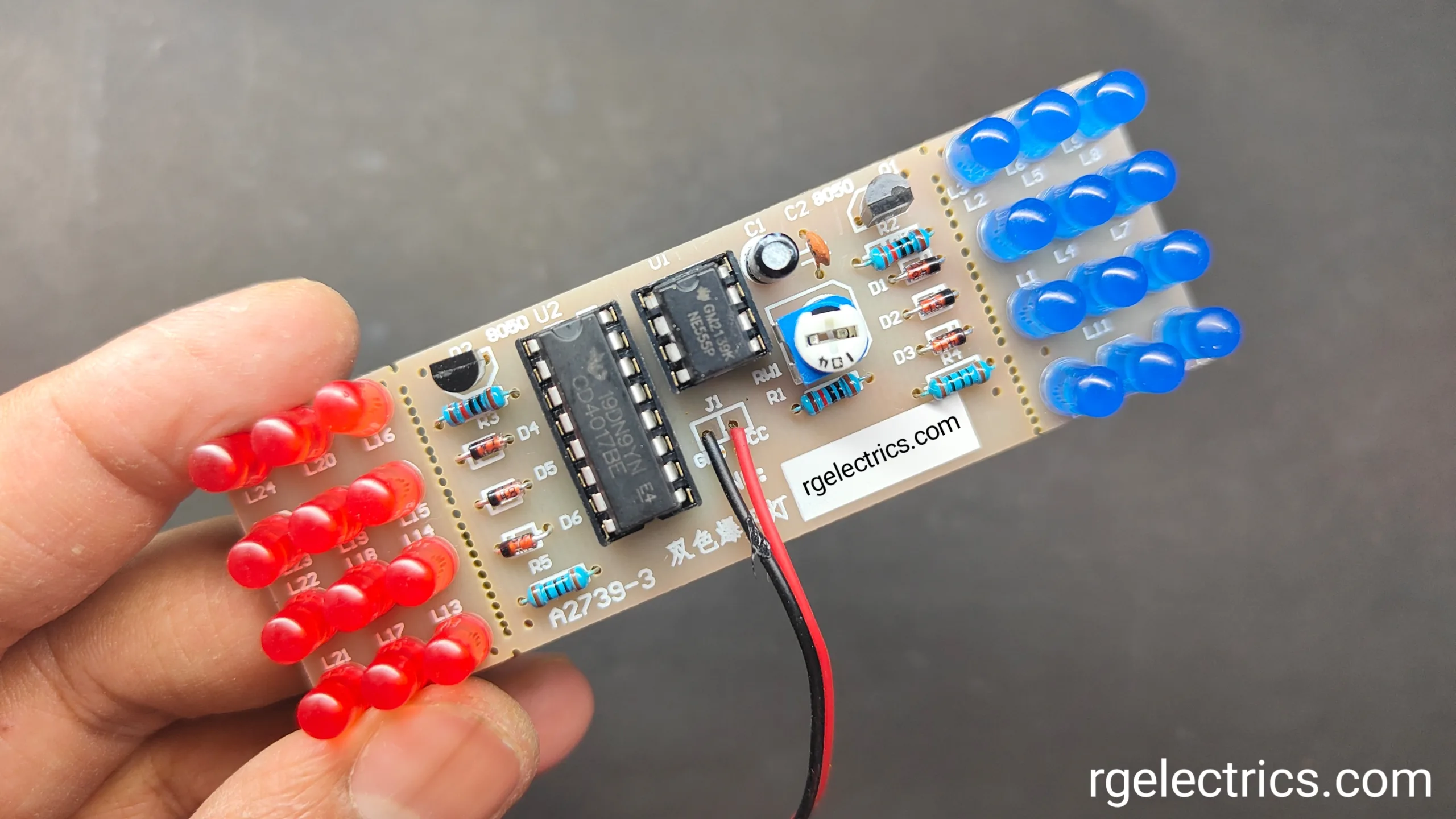
This circuit is a dual-color flashing light system, designed using a NE555 timer and a CD4017 decade counter. The primary function of the circuit is to alternate the flashing of two sets of LEDs—likely red and blue—creating a visually appealing effect. The NE555 operates in an astable mode, generating a clock signal that drives the CD4017. The CD4017, a decade counter, sequentially activates its outputs with each clock pulse from the timer. By using diodes to combine specific outputs, the circuit alternates between triggering two transistors (Q1 and Q2).
These transistors control the current flow to two separate LED arrays, making them flash alternately. The flashing rate can be adjusted using a potentiometer in the 555 timer’s circuit, which modifies the clock frequency. This type of circuit is commonly used in decorative lighting, signaling devices, or visual displays.
Component Required:
| S.No | Components | Value | Qty. |
|---|---|---|---|
| 1. | IC | NE555, CD4017 | 1, 1 |
| 2. | Transistor | S8050 | 2 |
| 3. | Diode | 1N4148 | 6 |
| 4. | Resistor | 10K, 100ohm | 3, 2 |
| 5. | Variable Resistor | 100K | 1 |
| 6. | Capacitor | 10uf, 0.01uf( 103) | 1, 1 |
| 7. | LED | Red, Blue | 12, 12 |
| 8. | Battery | 9V | 1 |
Circuit Diagram:

Circuit Explain:
Key Components:
- U1 – NE555 Timer:
- R1, RW1 (100k pot), and C1 form an astable multivibrator circuit, which generates a clock signal. The frequency can be adjusted by varying RW1 (the potentiometer).
- The output of the 555 timer (pin 3) sends a clock pulse to the CD4017 (pin 14).
- U2 – CD4017 Decade Counter:
- The CD4017 is a 10-stage decade counter. It takes the clock pulse from the 555 timer and activates one of its outputs sequentially (Q0 to Q9) for each clock pulse.
- Diodes D1 to D6 (1N4148) are used to combine certain outputs from the CD4017, controlling the transistors Q1 and Q2.
- Q1 and Q2 – Transistors (8050):
- Q1 and Q2 are used to drive two sets of LED arrays.
- The output of the CD4017, through the diodes, alternately triggers these transistors, allowing current to flow through either set of LEDs.
- The LEDs (L1–L24) are arranged into two groups, likely representing two different colors (red and blue).
- LED Arrays:
- The LEDs are connected in series-parallel arrangements in two sets, each controlled by one transistor (Q1 and Q2).
- One set of LEDs (L1 to L12) could represent red LEDs, while the second set (L13 to L24) could represent blue LEDs.
Operation:
- The 555 timer generates a clock signal, which is sent to the CD4017.
- The CD4017 outputs sequentially trigger certain diodes and, through them, activate Q1 or Q2.
- Q1 drives the first set of LEDs (L1–L12), while Q2 drives the second set (L13–L24).
- As the CD4017 cycles through its outputs, the LEDs will alternately flash, creating a red and blue flashing effect.
Adjustable Flash Rate:
- The flash rate can be adjusted by changing the resistance of RW1. This changes the frequency of the clock pulse generated by the NE555, thus controlling how fast the LEDs alternate.
Applications:
The NE555 and CD4017-based double-color flashing light circuit has several practical applications, including:
- Decorative Lighting:
- This circuit can be used in decorative lighting systems, such as in homes, shops, or during festive seasons to create alternating red and blue flashing effects.
- LED Signs and Displays:
- It can be applied in animated LED signs or displays where alternating light patterns are needed to grab attention, such as advertising boards or digital displays.
- Warning or Emergency Signals:
- The circuit can be used in warning systems or emergency vehicles, where alternating lights (e.g., red and blue) are essential for visibility and signaling.
- Toys and Gadgets:
- It can be incorporated into toys or electronic gadgets that require visual feedback with flashing lights for interactive play or alert mechanisms.
- Visual Indicators:
- This circuit can serve as a visual indicator in industrial equipment or electronics, where alternating lights signal operational status or warnings.


