Table of Contents
Introduction:
The NE555 blinking multiple LED light circuit uses the NE555 timer integrated circuit (IC) to create a flashing or blinking effect on a set of LEDs. The NE555 operates in astable mode, continuously switching between HIGH and LOW states, generating a square wave. This wave drives the LEDs, making them blink at a rate determined by the timing components (resistors and capacitors) connected to the IC.
In this circuit, resistors and capacitors connected to pins 6 and 2 set the oscillation frequency, while the output (pin 3) controls a series of LEDs, each protected by a current-limiting resistor. The circuit can be powered by a DC voltage between 5V and 12V, offering flexibility for different power sources.
This simple yet effective design is commonly used in visual indicators, decorations, or educational projects to demonstrate how 555 timers work in basic electronics. The blinking rate can be adjusted by changing the resistor and capacitor values.
Component details:
| S.no | Components | Value | Qty |
|---|---|---|---|
| 1. | Time IC | NE555 | 1 |
| 2. | Resistor | 10K, 220 ohm | 1, 10 |
| 3. | Capacitor | 10uf, 10nf | 1, 1 |
| 4. | LED | – | 10 |
| 5. | Battery | 5V-12V | 1 |
| 6. | Variable resistor | 100K | 1 |
NE555 Pinout:

The NE555 timer IC is an 8-pin chip commonly used for generating precise timing and oscillation in circuits. Here’s a description of the pinout:
- GND (Pin 1): Ground, connected to the negative side of the power supply.
- VCC (Pin 8): Supply voltage, connected to the positive side of the power supply. It typically ranges from 4.5V to 15V, depending on the application.
- DIS (Pin 7): Discharge pin. It’s connected to the timing capacitor, and discharges it when the output is low (used in astable and monostable modes).
- OUT (Pin 3): Output pin. Provides the output signal (either high or low) depending on the timer’s state.
- RST (Pin 4): Reset pin. If pulled low, it resets the timer and forces the output low. Usually tied to VCC when not used.
- THRS (Pin 6): Threshold pin. It compares the voltage of the capacitor with 2/3 of VCC. If the threshold exceeds this value, the output switches.
- TRIG (Pin 2): Trigger pin. A low voltage (<1/3 of VCC) on this pin causes the output to go high. Used to start the timing cycle.
- CV (Pin 5): Control voltage. Allows external adjustment of the internal reference voltage (usually connected to ground via a capacitor for stability).
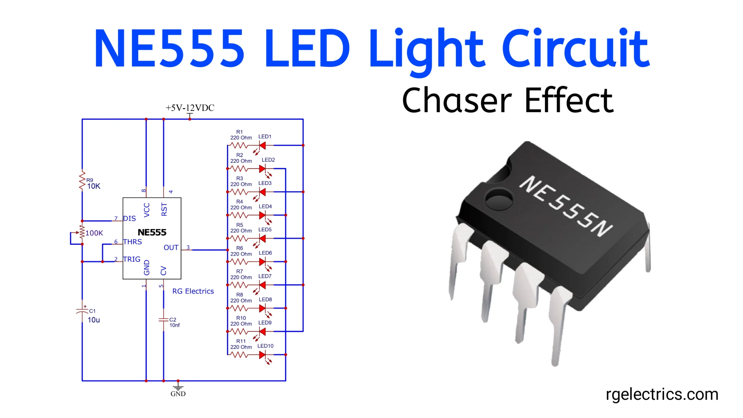
Circuit Diagram:

Working Explaination:
- 555 Timer (NE555): This is the main IC used in the circuit, operating in astable mode, which continuously toggles its output between HIGH and LOW states.
- Resistors and Capacitors:
- R9 (10K ohms) and R7 (100K ohms): These resistors set the timing for the 555 timer along with capacitor C1 (10uF). They determine the frequency at which the LEDs blink.
- C2 (10nF): This capacitor helps stabilize the 555 timer’s operation.
- Output to LEDs:
- The output pin (pin 3) of the 555 timer is connected to a set of LEDs (LED1 to LED10), each in series with its own current-limiting resistor (R1 to R11, each 220 ohms).
- When the output is HIGH, the LEDs are driven, and depending on the circuit configuration, they may light up in a specific sequence or all together.
- Power Supply:
- The circuit operates with a DC voltage ranging from +5V to +12V, as indicated at the top of the schematic.
Applications:
- Decorative Lighting: Applied in decorative items like LED strips or light displays where blinking or flashing lights create dynamic visual effects.
- Learning and Experimentation: Ideal for educational purposes to teach students or hobbyists about timing circuits, the functionality of the NE555 timer, and basic electronics principles.
- Toys and Gadgets: Used in toys or novelty gadgets to add flashing lights, making them more engaging and interactive.
- LED Chasers/Sequencers: With slight modifications, the circuit can be used to create running or chasing light effects, useful in advertising displays or art installations.