Table of Contents
Introduction
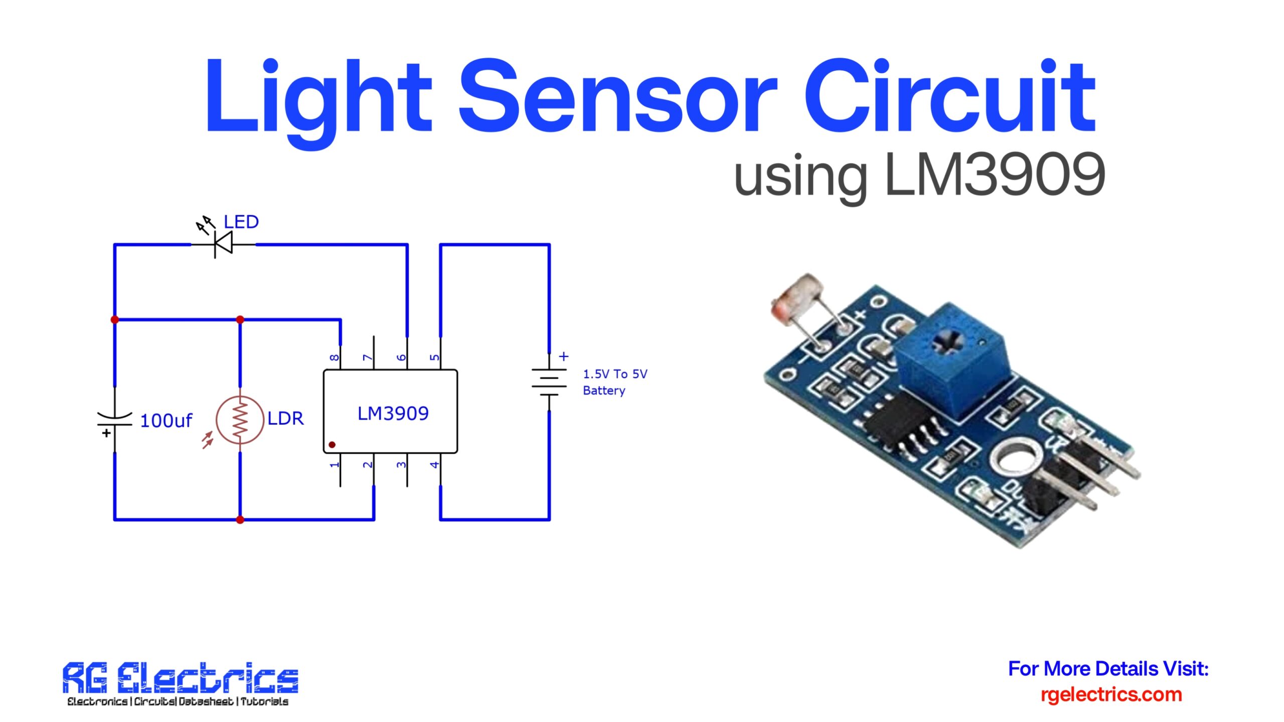
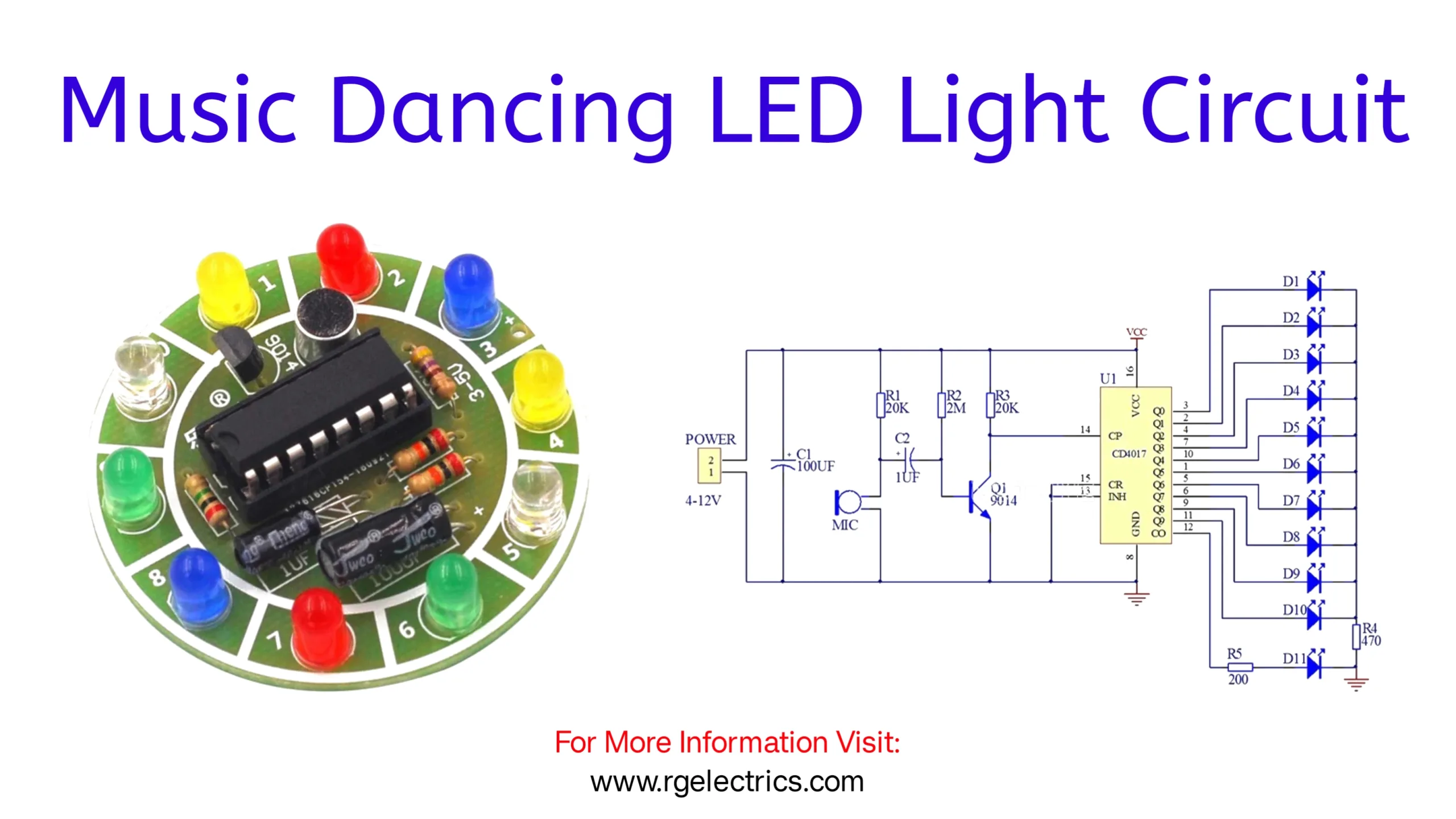
The Music Dancing LED Light Circuit is a simple yet exciting project that synchronizes LED lights with sound or music, creating an eye-catching visual effect. This circuit uses a microphone to detect sound waves and a transistor to amplify the signal, which is then fed to a CD4017 decade counter IC. The IC sequentially lights up LEDs in response to the sound pulses, producing a dancing LED effect. Powered by a 4–12V supply, the circuit is ideal for decorative lighting, parties, or DIY projects. It demonstrates basic electronics principles like amplification, signal processing, and sequential switching in an engaging way.
Components List
Passive Components:
- Resistors:
- R1: 20 kΩ
- R2: 2 MΩ
- R3: 20 kΩ
- R4: 470 Ω
- R5: 200 Ω
- Capacitors:
- C1: 100 μF (Electrolytic Capacitor)
- C2: 1 μF (Electrolytic Capacitor)
Active Components:
- Microphone (Electret MIC):
- Detects sound signals.
- Transistor:
- Q1: 9014 NPN Transistor (used for amplification of audio signal).
- IC:
- CD4017 (Decade Counter IC with 10 outputs).
- LEDs:
- D1 to D11: Standard LEDs (any color, e.g., blue or red).
Power Supply:
- Voltage Source:
- 4V to 12V DC power supply.
Miscellaneous:
- Connecting wires and PCB or Breadboard:
- For assembling the circuit.
C9014 Pinout

CD4017 Pinout

Circuit Diagram
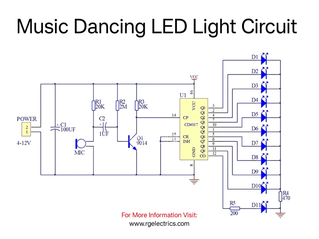
This circuit is a Music Dancing LED Light Circuit, which lights up LEDs in synchronization with sound or music input. Here’s a breakdown of the components and their functions:
Components:
- Microphone (MIC):
- Detects sound waves and converts them into small electrical signals.
- Acts as the input sensor for the circuit.
- Capacitors (C1 and C2):
- C1 (100μF): Filters the power supply to provide smooth voltage to the circuit.
- C2 (1μF): Couples the audio signal from the microphone to the next stage.
- Resistors (R1, R2, R3, R4, and R5):
- R1 (20KΩ): Sets the sensitivity of the microphone’s signal.
- R2 (2MΩ): Works as a pull-up resistor to stabilize the transistor circuit.
- R3 (20KΩ): Adjusts the signal before it reaches the IC.
- R4 (470Ω) and R5 (200Ω): Limit current to the LEDs to protect them from overcurrent.
- Transistor (Q1 – 9014):
- Amplifies the weak electrical signal from the microphone.
- IC (CD4017 – Decade Counter):
- A decade counter IC that lights up LEDs one by one in a sequence based on the clock signal it receives.
- It has 10 outputs (Q0 to Q9), but not all are used in this circuit.
- LEDs (D1 to D11):
- Visual output of the circuit.
- These LEDs light up in a dancing pattern based on the audio input.
- Power Supply:
- Provides a voltage of 4V to 12V for the circuit.
Working Principle
- Audio Signal Detection:
- The microphone detects the sound or music and generates a weak electrical signal.
- Signal Amplification:
- The transistor (Q1) amplifies this weak signal to a level that can trigger the IC (CD4017).
- Clock Signal Generation:
- The amplified signal from the transistor acts as a clock pulse for the CD4017 IC.
- Sequential LED Lighting:
- The CD4017 counter IC receives the clock pulses and activates its outputs (Q0 to Q9) sequentially.
- Each activated output lights up a corresponding LED.
- LED Display:
- As the outputs are triggered in sequence, the LEDs light up in a dancing pattern, synchronized to the music or sound input.
Applications
- Decorative lighting for parties.
- Visual indicators in music players or sound-sensitive projects.