Table of Contents
Introduction
An LED dimmer circuit allows you to adjust the brightness of an LED, providing flexibility and control for various applications. It is a versatile and practical project that finds use in both educational and real-world scenarios. Using an Arduino microcontroller, the project becomes straightforward and customizable, allowing precise control over the LED brightness based on user input.
LED dimming is achieved through Pulse Width Modulation (PWM), a technique where the average power delivered to the LED is varied by turning the signal on and off at a rapid pace. This method is energy efficient and extends the life of the LED. Moreover, the project demonstrates how to interface analog components, such as a potentiometer, with the digital processing capabilities of the Arduino. This article provides a comprehensive guide to building an LED dimmer circuit, including the required components, detailed circuit explanation, step-by-step instructions, Arduino code, troubleshooting tips, and practical applications in day-to-day life or professional settings.
Components Required
The following table lists the components required for the project:
| Component | Quantity | Description |
|---|---|---|
| Arduino Uno | 1 | Microcontroller board for processing signals |
| LED (any color) | 1 | Light-emitting diode for dimming demonstration |
| 220-ohm resistor | 1 | Limits current to protect the LED |
| 10k-ohm potentiometer | 1 | Adjustable resistor to control brightness |
| Breadboard | 1 | Prototyping board for easy circuit assembly |
| Jumper wires | As needed | Connects components on the breadboard |
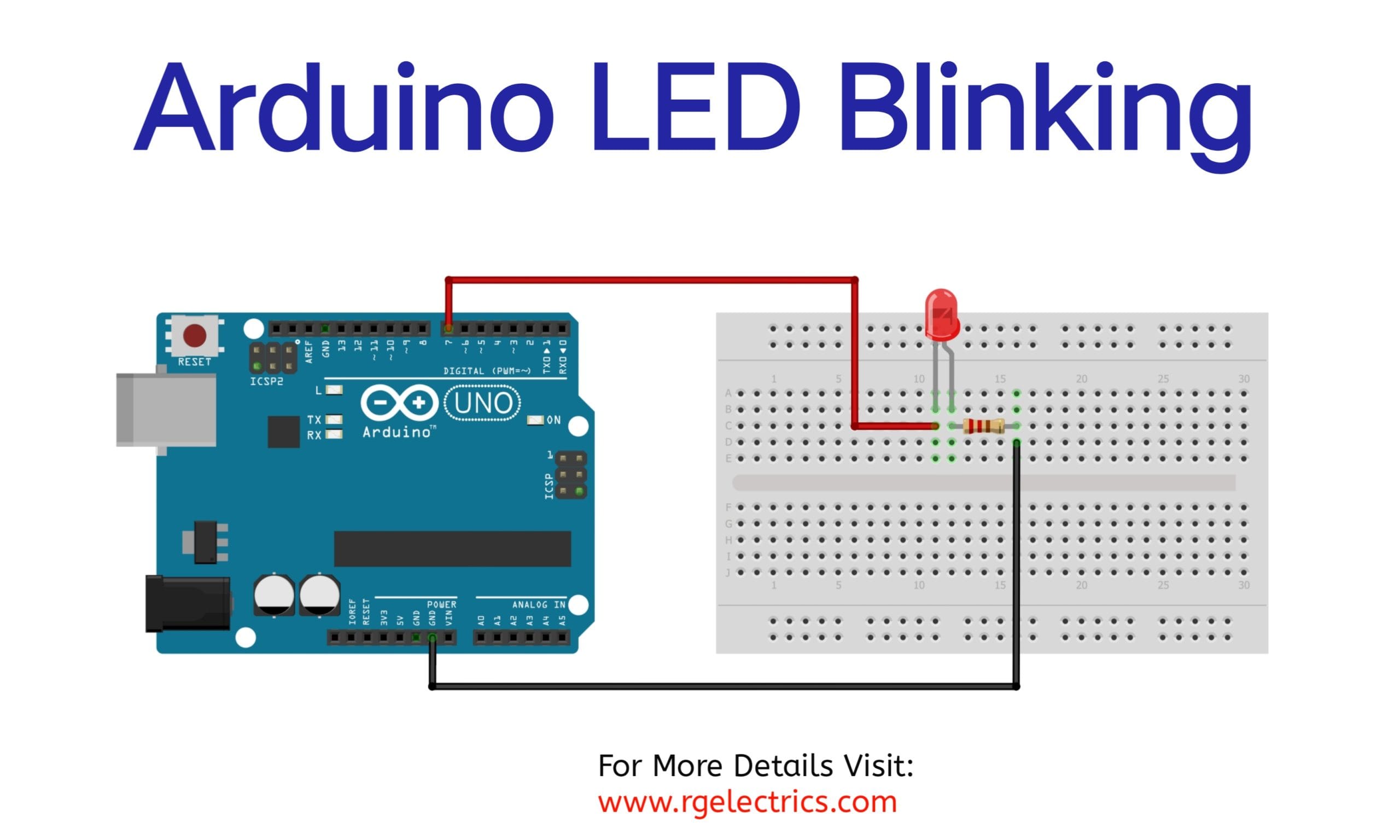
Schamatic

Circuit Explanation
The LED dimmer circuit utilizes a potentiometer to control the brightness of the LED. The potentiometer acts as a voltage divider, generating an analog signal that the Arduino reads through its analog input pin. This signal is then mapped to a PWM (Pulse Width Modulation) value, which the Arduino uses to control the LED brightness via the analogWrite() function.
Step-by-Step Circuit Assembly:
- Place the potentiometer on the breadboard.
- Connect one terminal of the potentiometer to the 5V pin on the Arduino.
- Connect the other terminal of the potentiometer to the GND pin on the Arduino.
- Connect the middle pin of the potentiometer to the Arduino’s analog input pin A0.
- Place the LED on the breadboard, ensuring the anode (long leg) is correctly oriented.
- Connect the anode of the LED to one end of the 220-ohm resistor.
- Connect the other end of the resistor to digital pin 9 of the Arduino.
- Connect the cathode (short leg) of the LED to the GND pin on the Arduino.
When the circuit is powered, the potentiometer’s position determines the analog voltage output. This value is processed by the Arduino and used to control the duty cycle of the PWM signal, which adjusts the brightness of the LED.
Arduino Code
The following Arduino sketch demonstrates how to control the LED brightness using the potentiometer:
// Define pin connections
const int ledPin = 9;      // PWM pin for LED
const int potPin = A0;     // Analog pin for potentiometer

void setup() {
  pinMode(ledPin, OUTPUT); // Set LED pin as output
  pinMode(potPin, INPUT);  // Set potentiometer pin as input
}

void loop() {
  // Read potentiometer value (0 to 1023)
  int potValue = analogRead(potPin);

  // Map the value to PWM range (0 to 255)
  int pwmValue = map(potValue, 0, 1023, 0, 255);

  // Write PWM value to LED
  analogWrite(ledPin, pwmValue);

  // Optional: Small delay for stability
  delay(10);
}
Code Explanation
- Pin Definitions: The LED and potentiometer pins are assigned to variables for easier reference.
- Setup Function: Initializes the pins as input or output.
- Loop Function: Continuously reads the potentiometer value, maps it to the PWM range, and adjusts the LED brightness using the
analogWrite()function.
Applications
The LED dimmer circuit has a variety of practical applications, including:
- Ambient Lighting: Provides adjustable mood lighting for homes and offices.
- Smart Lighting Systems: Forms the basis of dimmable smart lighting solutions.
- Prototyping and Testing: Useful for testing LED brightness levels in electronic projects.
- Learning Tool: Helps beginners understand analog-to-digital conversion and PWM control.
- Decorative Projects: Ideal for artistic installations requiring dynamic lighting effects.
Troubleshooting Tips
- LED Not Lighting Up:
- Ensure the LED is connected correctly (anode to the resistor, cathode to GND).
- Check all jumper wire connections for proper contact.
- Brightness Not Changing:
- Verify the potentiometer connections and functionality.
- Check the analog input pin (A0) for proper voltage readings.
- Code Issues:
- Ensure the correct board and port are selected in the Arduino IDE.
- Verify the code is uploaded successfully to the Arduino.
Conclusion
Building an LED dimmer circuit using Arduino is an excellent way to explore the basics of electronics and programming. This project demonstrates the use of analog-to-digital conversion and PWM control, key concepts in modern electronics. With the flexibility offered by Arduino, this simple circuit can be expanded to control multiple LEDs or integrated into larger systems, such as home automation or decorative lighting projects. By following the steps outlined in this article, you can successfully create your own LED dimmer and gain valuable hands-on experience.