Table of Contents
Introduction:
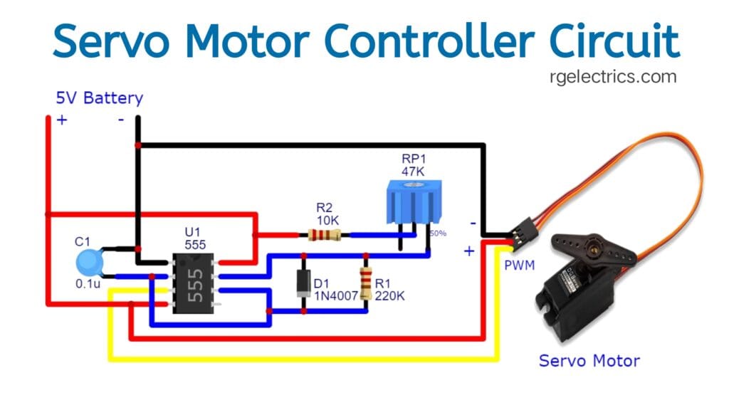
To build a servo motor controller circuit using NE555 timer IC, we will be using the NE555 in astable mode to generate pulse-width modulation (PWM) signals. A servo motor operates by receiving PWM signals, where the width of the pulse determines the angular position of the motor’s shaft. The NE555 timer can produce these PWM signals, controlling the servo position. servo motor controller using 555 timer IC. A servo motor is an actuator used to control angular position, velocity, and acceleration. The servo motor works on PWM principles, which means that the angle of its rotation is constrained by the duration of the pulse applied to its control pin.
Components Details:
| S.No | Components | Value | Quantity |
|---|---|---|---|
| 1. | IC | NE555 | 1 |
| 2. | Variable Resistor | 47K | 1 |
| 3. | Resistor | 220K,10K | 1,1 |
| 4. | Capacitor | 0.1uf | 1 |
| 5. | Servo Motor | – | 1 |
| 6. | Diode | 1N4007 | 1 |
| 7. | DC Supply | 5V | 1 |
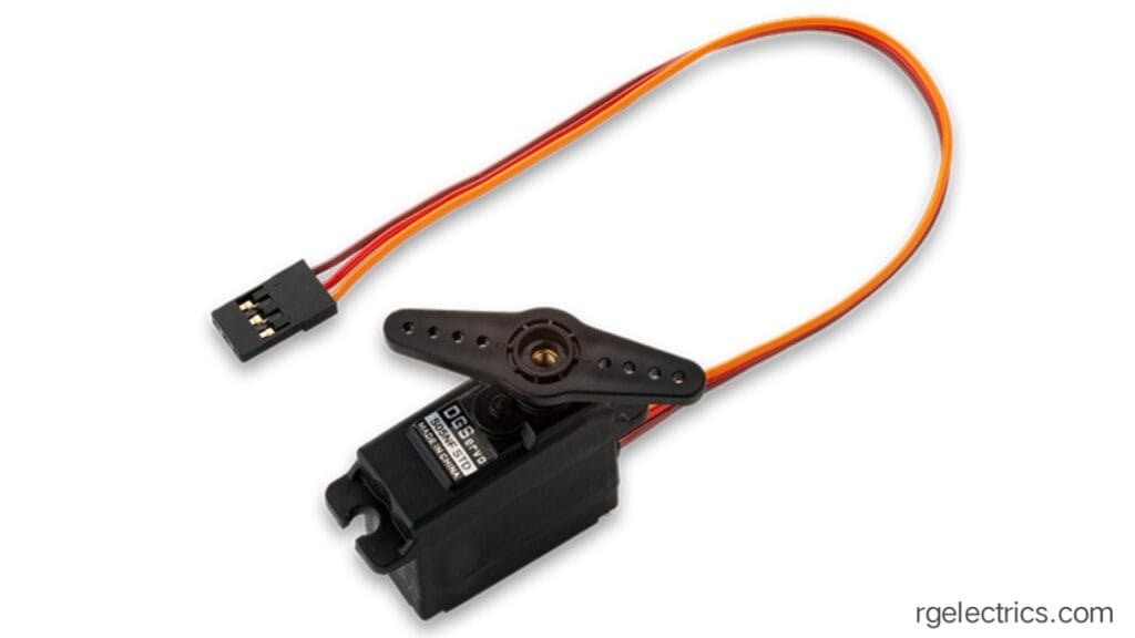
Servo Motor:
A servo motor is a rotary actuator or motor that allows for precise control of angular or linear position, velocity, and acceleration. It consists of a DC motor, a position control system (often a potentiometer for feedback), and an integrated circuit (IC) to control the motor’s behavior. Servo motors are widely used in applications requiring precise movement, such as robotics, RC vehicles, and automation systems.
Key Components of a Servo Motor:
- DC Motor: This generates the rotational motion.
- Gear System: A set of gears reduces the motor’s speed and increases torque, which is essential for precision control.
- Control Circuit: This interprets the input control signals and adjusts the motor’s position.
- Position Sensor (usually a Potentiometer): Provides feedback to the control circuit about the current position of the motor.
How a Servo Motor Works:
Servo motors are controlled by Pulse Width Modulation (PWM) signals. The servo motor reads these signals to determine the desired position of its output shaft. The length of the PWM pulse determines the angle to which the servo motor moves.
- PWM Signal: Typically, servo motors work with a pulse width of 1 ms to 2 ms at a frequency of 50 Hz.
- 1 ms pulse: Positions the servo at 0°
- 1.5 ms pulse: Positions the servo at 90° (middle).
- 2 ms pulse: Positions the servo at 180°.
These values may vary slightly depending on the specific servo model, but this is the general principle.
Types of Servo Motors:
- Positional Rotation Servo: This type rotates within a limited angle range (usually 0° to 180°). It’s the most commonly used type of servo motor.
- Continuous Rotation Servo: Unlike positional rotation servos, these can rotate continuously in either direction, acting like a DC motor with speed control rather than position control.
- Linear Servo: It moves in a straight line, converting rotational motion into linear motion through a mechanism like a lead screw.
Applications:
- Robotics: For controlling joints and movements.
- RC Vehicles: Used in steering, throttle, and other controls.
- CNC Machines: To control precise movement of tool heads.
- Automation Systems: In various automated equipment for precise movement.
Servo motors are popular because of their simplicity, reliability, and ability to provide smooth, precise control.
NE555:
The NE555 is one of the most popular and versatile integrated circuits (ICs) used in electronics. It is a timer IC that can be configured to generate accurate time delays or oscillations. The NE555 can be used in monostable, astable, and bistable modes, making it useful in various applications like pulse generation, PWM (pulse-width modulation), timers, and oscillators.

Key Features of NE555 Timer IC:
- Operates from a wide range of supply voltages (4.5V to 15V).
- Output can drive up to 200 mA.
- Adjustable duty cycle in astable mode.
- Accurate time delays and oscillations.
- Low cost and easy to use.
Pin Configuration of NE555 (8 Pins):
- Pin 1 (GND): Ground, connected to the negative terminal of the power supply.
- Pin 2 (Trigger): Starts the timing interval when the voltage drops below 1/3 of the supply voltage (Vcc).
- Pin 3 (Output): Provides the output signal, either high or low.
- Pin 4 (Reset): Resets the timing cycle when connected to ground. Usually connected to Vcc to disable the reset function.
- Pin 5 (Control Voltage): Allows the modulation of the threshold and trigger levels. If not used, it’s connected to ground via a 100nF capacitor.
- Pin 6 (Threshold): Ends the timing interval when the voltage exceeds 2/3 of the supply voltage (Vcc).
- Pin 7 (Discharge): Discharges the timing capacitor to ground in astable and monostable modes.
- Pin 8 (Vcc): Power supply, connected to the positive terminal of the power supply.
Potentiometer:
Use a potentiometer between Vcc and GND to adjust the voltage applied to the timing network, which will adjust the pulse width of the output signal, controlling the servo’s position.
Applications of NE555:
- Pulse generation (timing circuits)
- PWM control (motor speed control, LED brightness control)
- LED flashers and blinkers
- Tone generators
- Timers (delayed turn-on or turn-off circuits)
- Frequency dividers
Circuit Diagram:

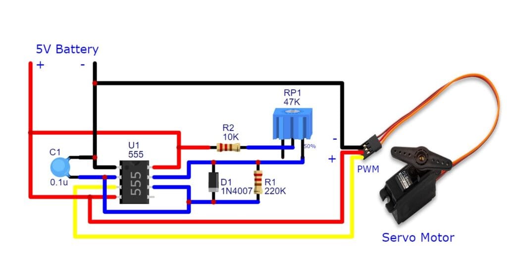
Circuit Description:
NE555 Timer in Astable Mode: The NE555 timer is configured in astable mode to generate a periodic PWM signal. The frequency of the signal should be around 50 Hz, as this is the standard for most hobby servos.
Resistors and Capacitors: The timing of the NE555 output (which generates the PWM signal) is determined by the combination of resistors and capacitors. Adjusting these components will control the pulse width and frequency.
PWM Signal for Servo Control:
- A typical servo expects a PWM signal of about 50 Hz, where the pulse width varies between 1 ms and 2 ms to move the shaft between 0° and 180°.
- Use a potentiometer to adjust the pulse width, which directly controls the servo position.
Working Principle:
NE555 PWM Signal: The NE555 will output a square wave signal, with the frequency set by the resistor and capacitor values. The pulse width is adjusted by the potentiometer, effectively controlling the servo motor’s shaft position.
Servo Movement: As the potentiometer is adjusted, the width of the pulses at Pin 3 of the NE555 changes, causing the servo to rotate to a corresponding position between 0° and 180°.
This circuit will allow you to control a small hobby servo using a potentiometer to vary the pulse width of the PWM signal generated by the NE555 timer IC.
Servo motors are used in:
- Robotics: For joint movements and precise control.
- RC Vehicles: To control steering, throttle, and rudders.
- CNC Machines: For precise tool positioning.
- Automation: In conveyors, sorting systems, and manufacturing processes.
- Drones: To control gimbals and camera stabilization.
- Home Automation: In automatic doors, curtains, and smart devices.
- Medical Devices: In robotic surgery and medical equipment.
- Camera Systems: For controlling focus, zoom, and pan/tilt mechanisms.