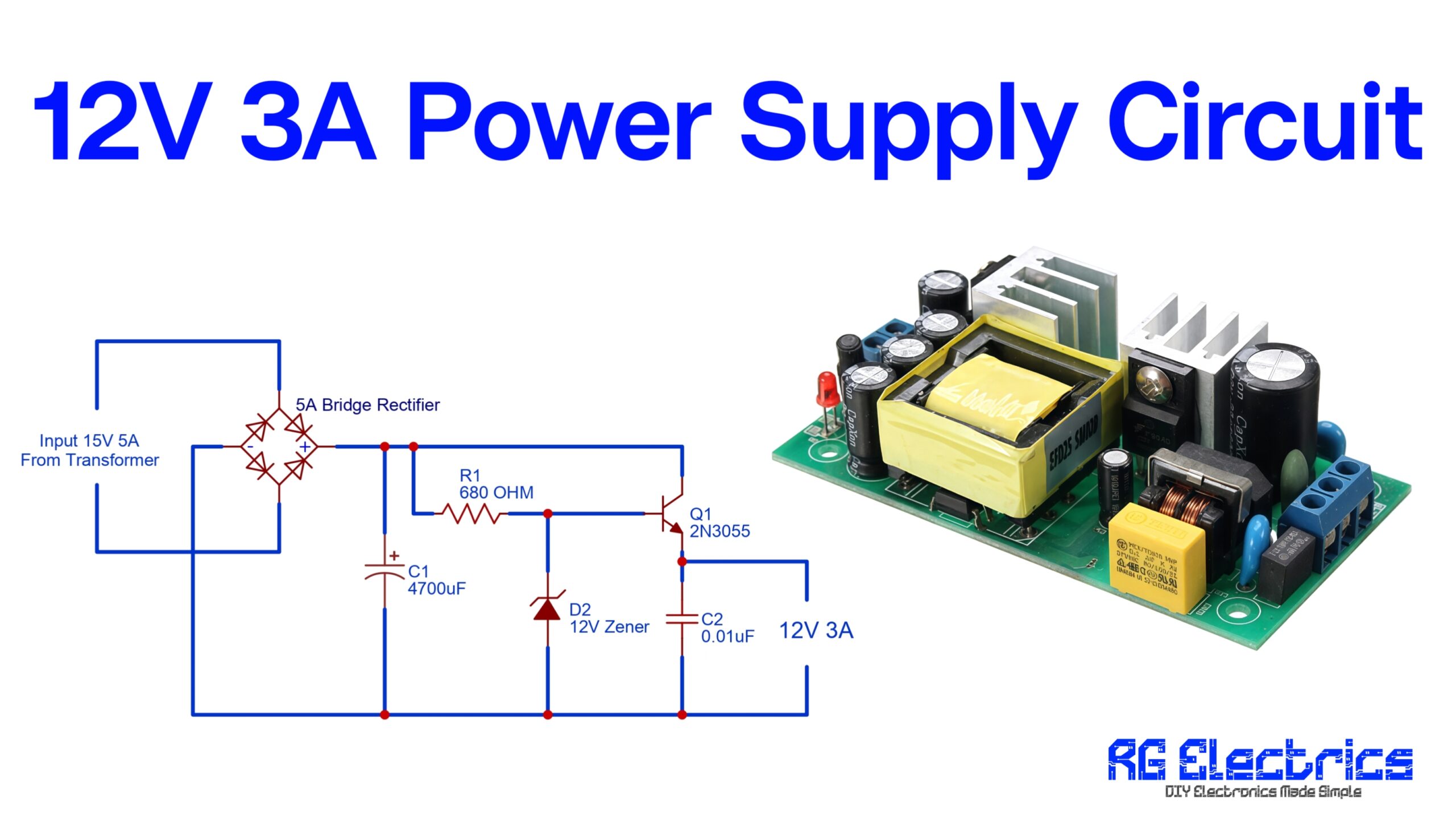
Table of Contents
Introduction
This dual power supply circuit provides ±35V DC outputs, making it ideal for powering audio amplifiers, operational amplifiers, and other electronics requiring a dual voltage source. It uses a center-tapped transformer to step down AC mains voltage, a bridge rectifier to convert AC to DC, and large filter capacitors to smooth and stabilize the output. Smaller capacitors filter high-frequency noise, ensuring clean power delivery. With a ground reference at the center tap, the circuit produces positive and negative voltage rails relative to ground. Fuses on both outputs protect against overcurrent, ensuring safe and reliable operation for various applications.
Components List
| S.no | Component | Value | Qty. |
|---|---|---|---|
| 1. | Transformer center-tapped | 30-0-30 | 1 |
| 2. | Diode 6A | 6A4 | 4 |
| 3. | Capacitor | 4700uf/50V, 100nf | 2,2 |
| 4. | Fuse | 6A | 2 |
Circuit Diagram
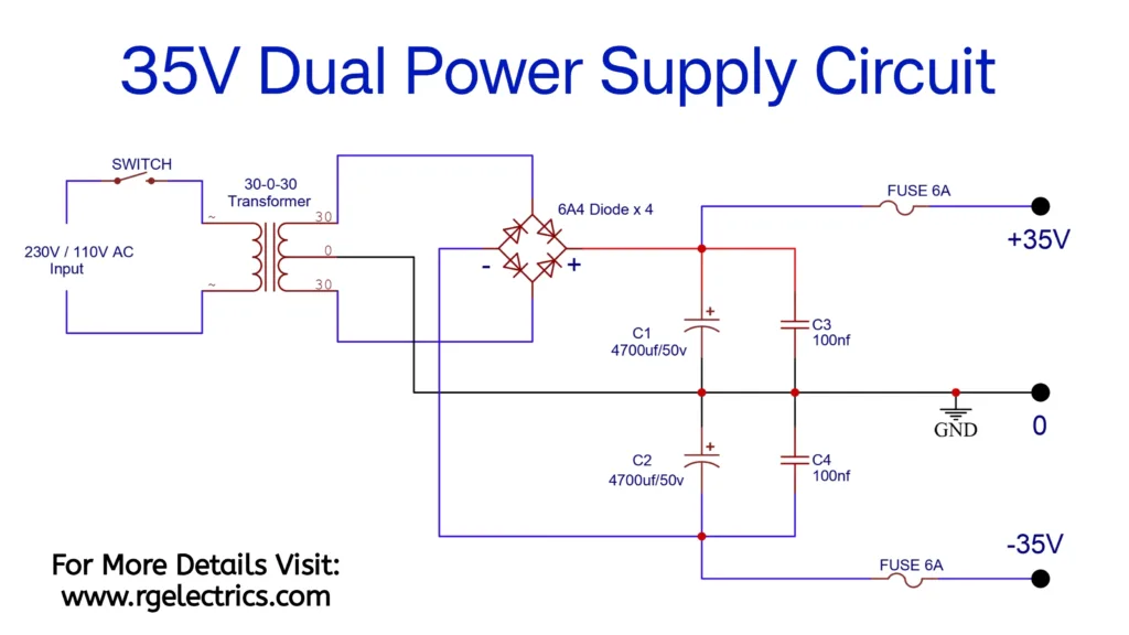
Circuit Explain
The dual power supply circuit shown provides both positive (+35V) and negative (-35V) DC voltages relative to a ground (0V) reference. This type of power supply is commonly used in electronics requiring dual voltage rails, such as operational amplifiers, audio amplifiers, and other analog circuits. Here’s a detailed explanation of how the circuit works:
1. AC Input and Transformer
- AC Voltage Input (230V/110V AC):
- The circuit receives mains AC voltage (110V or 230V depending on the region).
- A switch is used to turn the power supply on or off.
- Transformer (30-0-30):
- The transformer steps down the high mains voltage to a lower voltage of 30V-0V-30V AC (center-tapped).
- The center tap acts as the ground (0V), while the other two terminals provide +30V AC and -30V AC with respect to the center tap.
2. Bridge Rectifier
- A bridge rectifier is made of four diodes (6A4 diodes rated for 6A current handling).
- The purpose of the bridge rectifier is to convert the AC voltage into pulsating DC voltage:
- The positive cycle of the AC signal flows through two diodes, creating a positive voltage at the output.
- During the negative cycle, the other two diodes conduct, creating a negative voltage at the output.
This results in two separate DC voltages:
- A positive DC voltage at the output terminal marked “+35V.”
- A negative DC voltage at the output terminal marked “-35V.”
3. Filtering Stage
- Electrolytic Capacitors (C1 and C2, 4700µF/50V):
- These large capacitors smooth the pulsating DC voltage from the rectifier into steady DC voltage.
- C1 smooths the positive voltage rail, while C2 smooths the negative voltage rail.
- Small Capacitors (C3 and C4, 100nF):
- These capacitors filter out high-frequency noise or ripples, ensuring a clean DC output.
4. Fuses
- Two 6A fuses are included, one in the positive rail and one in the negative rail, for overcurrent protection.
- If the load draws excessive current, the corresponding fuse will blow, protecting the circuit and connected devices.
5. Dual Outputs
- The circuit provides:
- A +35V output relative to the ground.
- A -35V output relative to the ground.
- These outputs can be used in circuits requiring dual power supplies (e.g., operational amplifiers and audio amplifiers).
Circuit Function Overview:
- AC to DC Conversion:
- The transformer steps down the AC voltage, and the bridge rectifier converts it to pulsating DC.
- Smoothing:
- The capacitors smooth the pulsating DC to steady DC voltages on both the positive and negative rails.
- Protection:
- Fuses protect the circuit from overcurrent conditions.
Applications
- Operational Amplifiers (Op-Amps)
- Audio Amplifiers
- Test and Measurement Equipment
- Powering Analog and Mixed-Signal Circuits