Table of Contents
Introduction
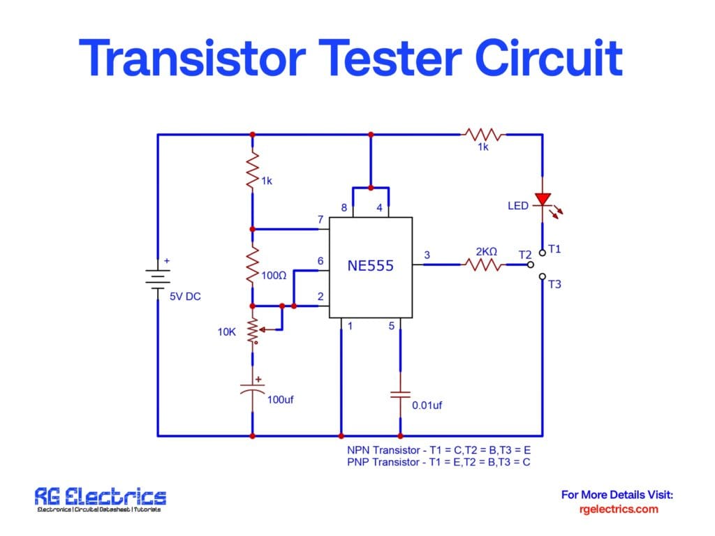
A transistor tester circuit is an essential tool for electronics enthusiasts and engineers to check whether a transistor is working correctly. This circuit, based on the NE555 timer IC, allows users to test both NPN and PNP transistors by observing the LED indicator. When a functional transistor is inserted into the circuit, the LED blinks, indicating that the transistor is operating correctly. This simple and effective circuit helps in quickly identifying faulty transistors without the need for complex testing equipment.
Circuit Components
| S.No | Component Name | Value | Quantity |
|---|---|---|---|
| 1 | NE555 Timer IC | – | 1 |
| 2 | Resistor | 1kΩ | 2 |
| 3 | Resistor | 100Ω | 1 |
| 4 | Resistor | 10kΩ | 1 |
| 5 | Resistor | 2kΩ | 1 |
| 6 | Capacitor | 100µF | 1 |
| 7 | Capacitor | 0.01µF | 1 |
| 8 | LED | – | 1 |
| 9 | Power Supply | 5V DC | 1 |
| 10 | Transistor Test Terminals | – | 1 set |
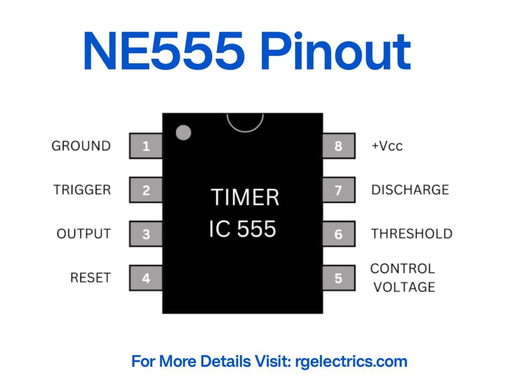
NE555 Pinout
Circuit Diagram
Circuit Explanation
The transistor tester circuit operates using the NE555 timer IC in astable mode. Below is a breakdown of how it functions:
- Oscillation Generation:
- The NE555 timer is configured to operate as an astable multivibrator, generating a continuous square wave signal.
- This oscillation is crucial as it acts as a test signal for the transistor under examination.
- Transistor Testing:
- The circuit has three terminals: T1, T2, and T3.
- For an NPN transistor:
- T1 = Collector, T2 = Base, T3 = Emitter.
- For a PNP transistor:
- T1 = Emitter, T2 = Base, T3 = Collector.
- When a transistor is inserted correctly and is in working condition, it allows current to pass, enabling the LED to blink.
- If the LED does not blink, the transistor is faulty or incorrectly placed.
- LED Indicator:
- The LED serves as a visual indicator to confirm transistor operation.
- A blinking LED signifies a functioning transistor, whereas a non-blinking LED indicates a defective transistor.
- Power Supply Considerations:
- The circuit operates efficiently on a 5V DC power source, making it suitable for use with battery packs or USB power.
Applications
- Quick transistor functionality testing.
- Identifying NPN and PNP transistor types.
- Educational purposes for learning transistor behavior.
- Troubleshooting electronic circuits.
This transistor tester circuit provides a simple yet effective way to check transistor functionality using an NE555 timer IC. It is easy to assemble and highly useful for DIY electronics projects and repair work.