

Table of Contents
Introduction
A touch sensor circuit is an electronic circuit that detects physical touch and activates an output. This type of circuit is widely used in modern electronics, including touch-activated switches, security systems, and interactive devices. Unlike mechanical switches, touch sensors provide a more durable and reliable method of user interaction, as they do not suffer from wear and tear due to moving parts. These circuits are commonly employed in applications where precise and seamless user input is required, such as in smartphones, home automation systems, and industrial controls.
The touch sensor circuit presented here operates using the popular NE555 timer IC in bistable mode. By utilizing high-value resistors, the circuit effectively senses small electric charges from a user’s touch to toggle an LED. This simple yet efficient design makes it an excellent choice for DIY projects, educational experiments, and practical implementations in electronic devices.
Circuit Components
| S.No | Component Name | Value | Quantity |
|---|---|---|---|
| 1 | NE555 Timer IC | – | 1 |
| 2 | Resistor | 10MΩ | 2 |
| 3 | Resistor | 330Ω | 1 |
| 4 | LED | – | 1 |
| 5 | Power Supply | 5V | 1 |
| 6 | Touch Probes | – | 1 set |
NE555 Pinout

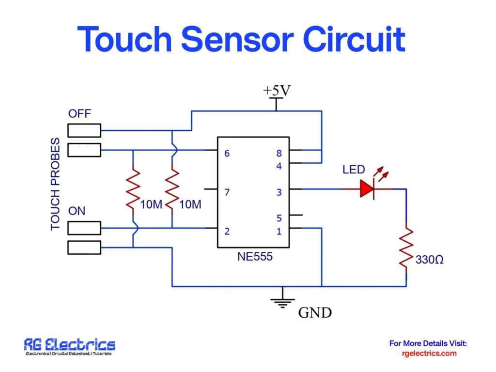
Circuit Diagram
Circuit Explanation
The touch sensor circuit works based on the operation of the 555 timer IC in bistable mode. Here’s how the circuit functions:
- Touch Detection:
- The circuit has two touch probes labeled ON and OFF.
- When a user touches the ON probe, a small current flows through the high-value 10MΩ resistor, providing a voltage trigger to the 555 timer.
- Timer Operation:
- The 555 timer changes its output state when triggered by the ON probe.
- This turns the LED ON, indicating activation.
- The circuit remains in this state until another action is performed.
- Turning OFF the Circuit:
- When the OFF probe is touched, the 555 timer gets another trigger and switches its output state.
- This turns the LED OFF, resetting the circuit.
- Resistors Role:
- The 10MΩ resistors limit the current flow, ensuring the circuit operates efficiently.
- The 330Ω resistor is connected in series with the LED to prevent excessive current from damaging it.
Applications
- Touch-activated switches.
- Security access control systems.
- Interactive electronic devices.
- Home automation systems.
This touch sensor circuit is a simple yet effective way to implement touch-based switching using a 555 timer IC. With minor modifications, it can be adapted for various real-world applications.


