Table of Contents
#1 Simple LED Flasher Circuit
Introduction
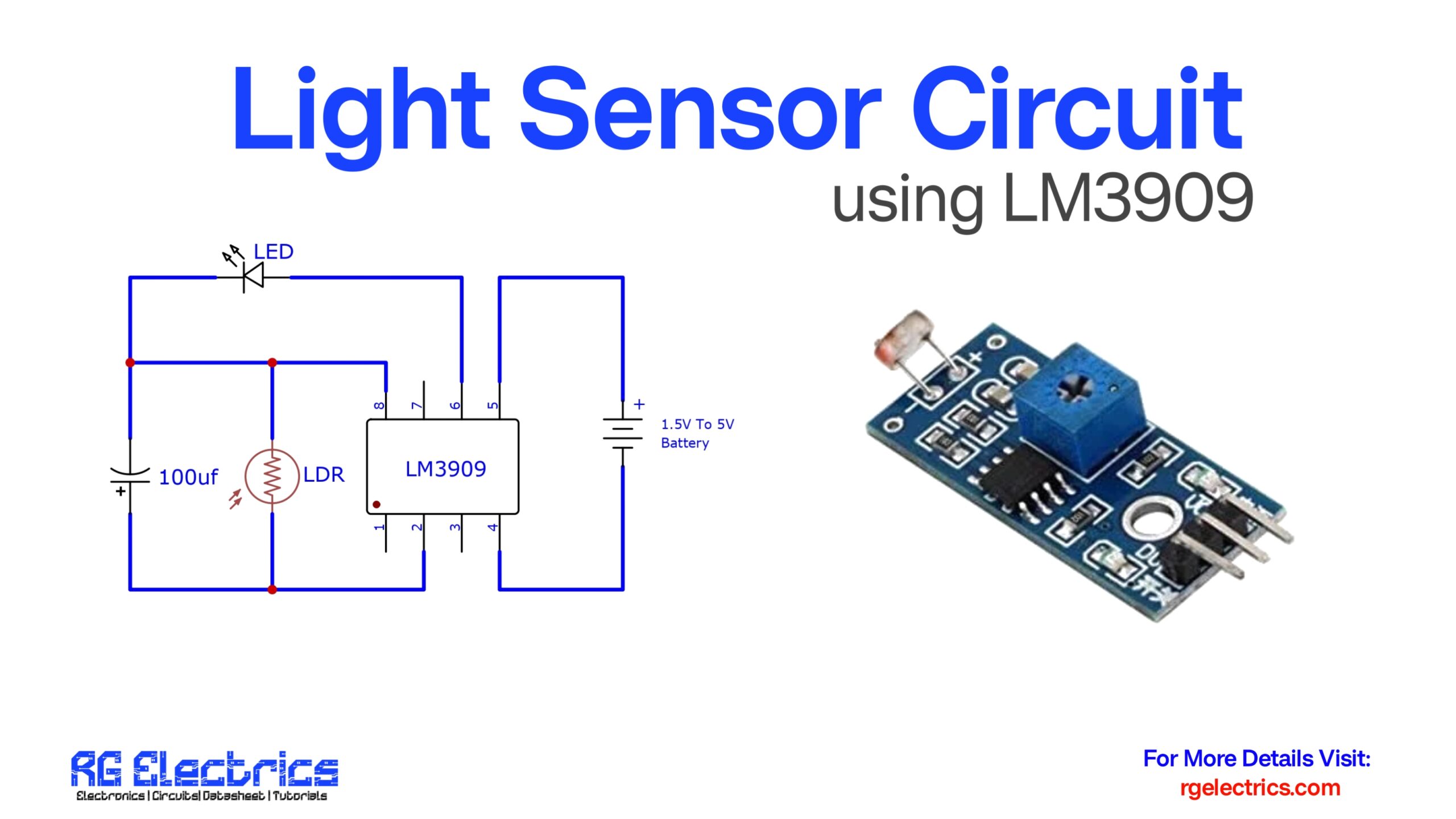
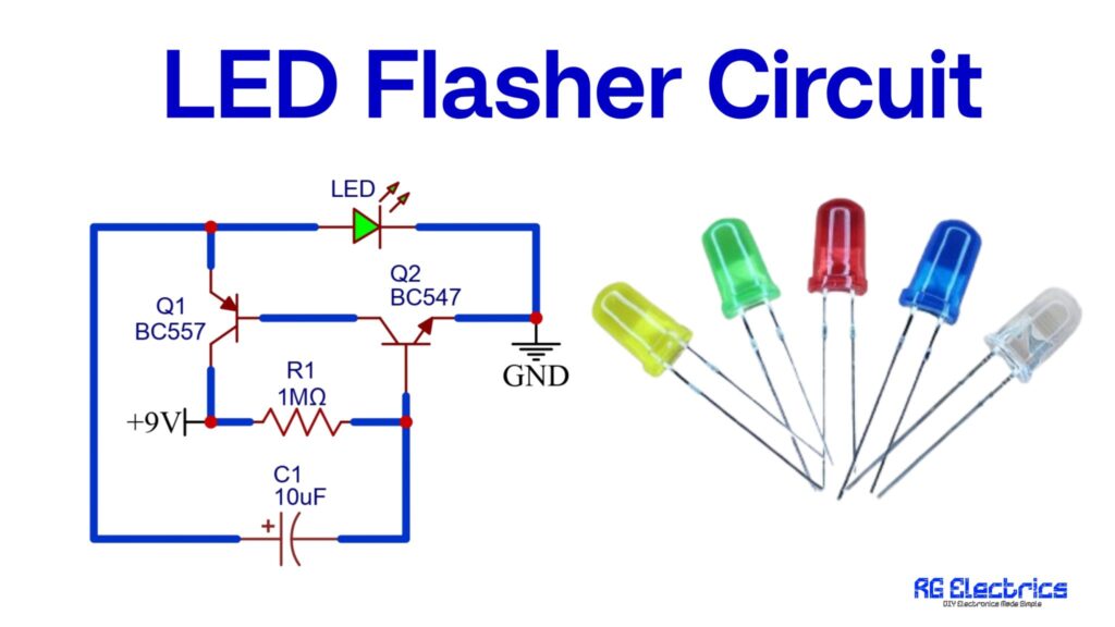
The LED Flasher Circuit is a simple electronic project used to make an LED blink at regular intervals. It is commonly built using a few basic components such as transistors, resistors, a capacitor, and an LED powered by a small battery. The main purpose of this circuit is to create a visual flashing effect that can be used in indicators, toys, decoration lights, and simple signaling systems. Unlike a steady glowing LED, this circuit automatically switches the LED ON and OFF repeatedly, attracting attention with its blinking pattern. It is a beginner-friendly project that helps students and hobbyists understand the basic concept of switching, timing, and capacitor charging-discharging in electronics. Due to its simplicity and low cost, it is widely used for educational and practical purposes.
Component Details
| Component | Specification/Value | Quantity | Function |
|---|---|---|---|
| Transistor Q1 | BC557 (PNP) | 1 | Acts as a switching transistor |
| Transistor Q2 | BC547 (NPN) | 1 | Drives the LED ON/OFF |
| Resistor R1 | 1 MΩ | 1 | Controls capacitor charging time |
| Capacitor C1 | 10 µF / 16V (Electrolytic) | 1 | Provides timing for LED flashing |
| LED | 5mm (Any Color) | 1 | Visual flashing indicator |
| Battery | 9V DC | 1 | Power supply for the circuit |
Circuit Diagram
Circuit Explain
This circuit works like an Astable Multivibrator that makes the LED flash continuously.
- At the beginning (Power ON):
The capacitor C1 is empty (discharged). - Charging Phase:
- C1 starts charging through resistor R1.
- While charging, the voltage across C1 changes the biasing of the transistors Q1 and Q2.
- LED ON:
- When C1 reaches a certain voltage, Q2 (NPN) turns ON.
- Current flows through the LED, and it glows.
- LED OFF:
- After some time, C1 discharges.
- When it discharges, Q2 turns OFF, cutting current through the LED, so the LED goes OFF.
- The cycle repeats again.
#2 Simple AC Line Detector Circuit using Bc547
Introduction
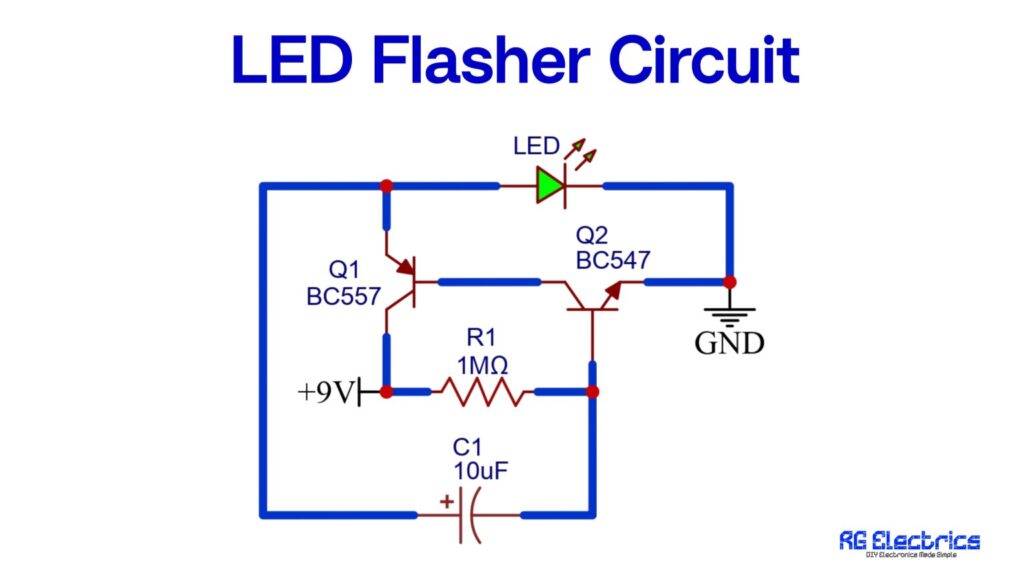
The AC line detector circuit is a handy non-contact voltage tester that helps detect the presence of alternating current (AC) in a wire or line without direct electrical contact. It is particularly useful for safely identifying live wires, checking for broken AC lines inside walls, or locating cable faults. This circuit works by sensing the electromagnetic field around AC lines using an antenna (a short piece of wire), which triggers a response from the components — turning ON a buzzer and an LED as indicators.
Unlike commercial testers that may be complex or expensive, this simple circuit is easy to build using readily available components and provides reliable results. It’s powered by a 9V battery, making it portable and safe to use in residential and field environments.
Components Details
| S.No | Component Name | Value/Specification | Quantity |
|---|---|---|---|
| 1 | Transistor | BC547 | 3 |
| 2 | Resistor | 220Ω (R1) | 1 |
| 3 | LED | Red or Green | 1 |
| 4 | Buzzer | 9V DC Buzzer | 1 |
| 5 | Antenna | Short Wire (5–10 cm) | 1 |
| 6 | Battery | 9V Battery | 1 |
| 7 | Connecting Wires | – | As needed |
Circuit Diagram
Circuit Explanation
The circuit employs three BC547 transistors (Q1, Q2, Q3) configured in a cascaded amplifier arrangement. Here’s a step-by-step explanation:
- Antenna Input: A short wire acts as an antenna and is responsible for picking up the electromagnetic field emitted by live AC wires nearby. This weak AC signal is enough to bias the base of Q1 (first transistor).
- Amplification Stage:
- When the antenna senses an AC field, Q1 gets slightly biased, allowing a small current to flow.
- This signal is amplified and fed into Q2, which further strengthens the signal and passes it to Q3.
- Each transistor stage multiplies the signal strength, effectively making the circuit highly sensitive.
- Output Indication:
- Once Q3 is fully turned ON, it completes the circuit for the LED and buzzer.
- The LED glows to provide a visual indication.
- The buzzer sounds, alerting the user of nearby AC voltage presence.
- Power Supply: The circuit is powered by a 9V battery, making it both portable and electrically isolated from the mains — hence, very safe.
This circuit does not require direct electrical contact with the wire being tested, making it a non-invasive tool. It only detects AC signals (typically 50/60 Hz).
#3 Clap Switch Circuit using NE555 Timer IC

Introduction
The Clap Switch is a simple yet fascinating electronics project that demonstrates sound detection and automatic switching. This circuit uses a condenser microphone to detect sound (like a clap) and a NE555 Timer IC to process the signal and switch an output device — in this case, an LED.
This kind of project is commonly used in sound-activated lights, appliances, or security systems. With its minimal components and ease of understanding, it’s ideal for electronics hobbyists and beginners looking to explore the fundamentals of analog signal detection and timer-based switching.
Components Required
| S.No | Component Name | Value | Quantity |
|---|---|---|---|
| 1 | NE555 Timer IC | — | 1 |
| 2 | Condenser Mic | — | 1 |
| 3 | Transistor | BC547 | 1 |
| 4 | Resistor | 1kΩ | 1 |
| 5 | Resistor | 47kΩ | 1 |
| 6 | Resistor | 100kΩ | 1 |
| 7 | Resistor | 220Ω | 1 |
| 8 | Capacitor | 10µF | 1 |
| 9 | LED | Red | 1 |
| 10 | Battery | 9V | 1 |
| 11 | Breadboard/Wires | — | As needed |
Circuit Diagram

Circuit Explanation
Working Principle:
The circuit operates by detecting a sharp sound pulse like a clap using a condenser microphone. The mic converts the sound into a small voltage signal. This signal is too weak to drive any load, so it is first amplified using a BC547 transistor. The amplified signal then triggers the NE555 timer IC, configured in monostable mode.
- Sound Detection:
- The condenser microphone picks up sound vibrations and produces a small AC signal.
- This signal is sent to the base of the BC547 transistor via a 1kΩ resistor (R1).
- Signal Amplification:
- The BC547 transistor amplifies the signal and acts as a switch.
- When sound is detected, it sends a short high pulse to pin 2 (trigger) of the NE555 IC.
- 555 Timer Response:
- NE555 is configured in monostable mode. Upon receiving the trigger, it switches its output (pin 3) to HIGH for a short duration.
- This ON time is controlled by R3 (100kΩ) and C1 (10µF).
- LED Activation:
- The HIGH output from pin 3 is fed through a 220Ω resistor (R4) to an LED.
- The LED lights up briefly to indicate the detection of a clap.
- Resetting:
- After a short delay (defined by RC timing), the output goes LOW again, turning the LED off.
- The circuit resets and becomes ready to detect the next clap.
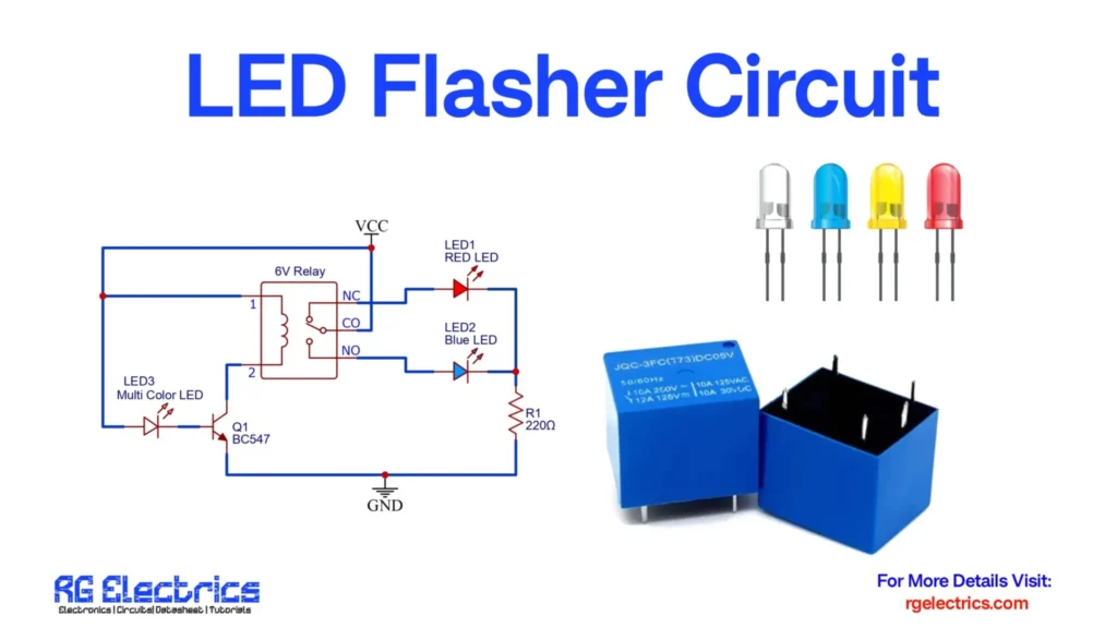
#4 LED Flasher Circuit Using Relay
Introduction
The LED Flasher Circuit Using Relay is a simple and fascinating electronic project that demonstrates how to create a blinking effect using basic components like a relay and a transistor. This circuit alternates LEDs between on and off states, making it perfect for decorative lighting, indicators, or DIY hobby circuits. With just a few easily available components, this setup can teach important concepts in electronics such as switching, current control, and relay operations.
Components Required
| S.No | Component Name | Value | Quantity |
|---|---|---|---|
| 1 | Relay | 6V | 1 |
| 2 | NPN Transistor | BC547 | 1 |
| 3 | Red LED | – | 1 |
| 4 | Blue LED | – | 1 |
| 5 | Multicolor LED | – | 1 |
| 6 | Resistor | 220Ω | 1 |
| 7 | Power Supply | 6V DC | 1 |
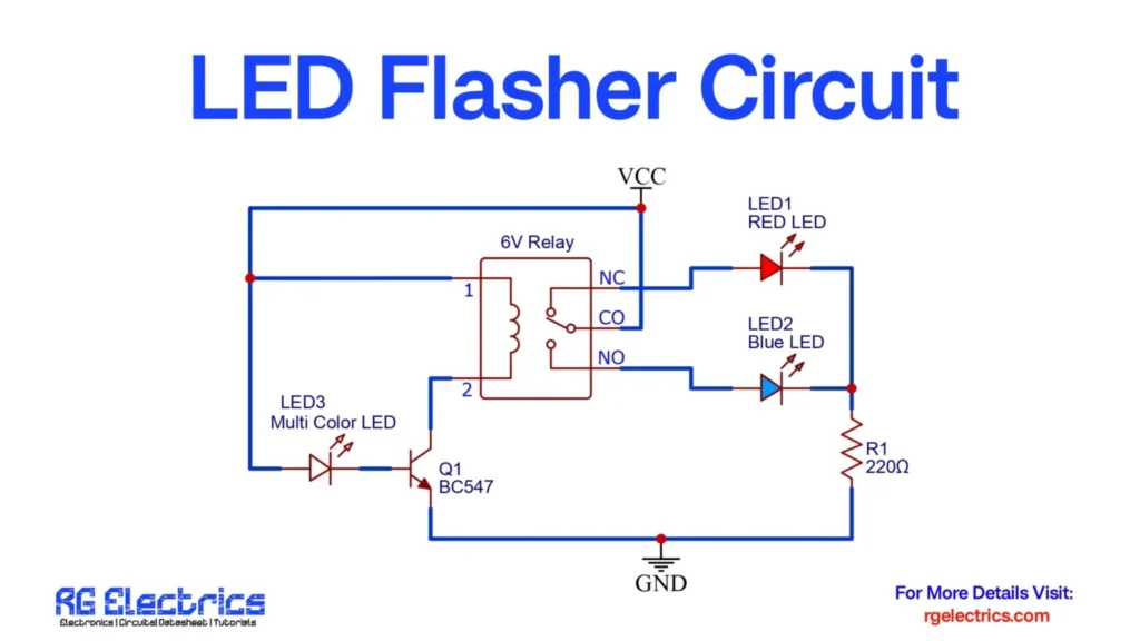
Circuit Diagram
Working Principle
The main working principle of this circuit is based on the switching mechanism of the relay controlled by the BC547 transistor. Here’s a breakdown of how it works:
1. Powering the Circuit
The circuit is powered using a 6V DC power supply connected at the VCC terminal.
2. Relay Coil Activation
When the circuit is powered, the base of the BC547 transistor (Q1) receives current through the multicolor LED3, turning it on. This allows current to flow from the collector to the emitter of the transistor, energizing the coil of the 6V relay.
3. Switching the Contacts
The relay has three key contacts:
- NC (Normally Closed)
- NO (Normally Open)
- CO (Common)
Initially, CO is connected to NC. When the relay is energized by the transistor, CO switches to NO.
4. Flashing LEDs
- In one state, LED1 (Red) is ON while LED2 (Blue) is OFF.
- In the alternate state, LED2 (Blue) turns ON and LED1 (Red) turns OFF.
- This alternating pattern continues as the relay is repeatedly energized and de-energized, resulting in a flashing effect.
- The multicolor LED3 gives an additional aesthetic element and also helps drive the transistor.
5. Current Limiting
The 220Ω resistor (R1) is used to limit the current to safe levels for the LEDs.
#5 Simple LED Blinking Circuit using NE555
Introduction:
An LED flashing circuit is a simple yet effective way to demonstrate the use of the NE555 timer integrated circuit (IC) in astable mode, where it generates continuous pulses. This circuit is widely used in hobby electronics, signaling applications, and as a fundamental introduction to timer ICs. The primary function of the circuit is to turn an LED on and off at regular intervals, creating a blinking or flashing effect.
The NE555 timer, a versatile and widely used IC, is the core of this circuit. It can be configured in different modes, and in this case, it is set to astable mode, meaning it operates without any stable state—continuously switching between high and low output. By using basic electronic components like resistors, capacitors, and LEDs, this circuit allows for easy control of the LED’s flashing rate through the manipulation of resistance and capacitance values.
This simple yet instructive circuit introduces basic timing concepts and is often the foundation for more advanced timing or pulse generation projects.
Component Details:
| S.No | Components | Value | Qty. |
|---|---|---|---|
| 1. | Time IC | NE555 | 1 |
| 2. | Capacitor | 10uf | 1 |
| 3. | Resistor | 1k, 100k | 1,1 |
| 4. | LED | – | 1 |
| 5. | Battery | 3.7V | 1 |
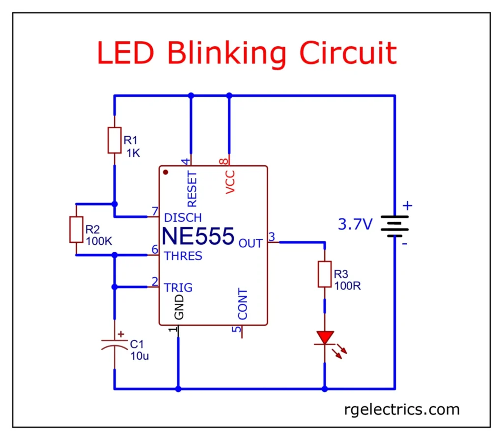
Circuit Diagram
Circuit Explaination:
Components:
- NE555 Timer IC: This is the main component, configured in astable mode, where it continuously switches between high and low states, creating a square wave.
- Resistors (R1, R2): R1 (1KΩ) and R2 (100KΩ) set the timing intervals for the LED flashes.
- Capacitor (C1): This 10μF capacitor helps determine the frequency of the LED flashing, working together with R1 and R2.
- LED: The light-emitting diode flashes on and off based on the NE555’s output.
- Resistor (R3): A current-limiting resistor (100Ω) protects the LED.
- Power Source: A 3.7V power supply, commonly a Li-ion battery, powers the circuit.
How it works:
- When power is applied, the NE555 timer continuously charges and discharges the capacitor (C1) through resistors R1 and R2.
- This oscillation between charging and discharging causes the output at pin 3 to switch between high and low.
- When pin 3 is high, the LED turns on, and when pin 3 is low, the LED turns off, causing it to flash at a regular interval.
This is a simple LED flasher circuit often used in hobby electronics.
#6 Simple Up/Down Fading LED Circuit using NE555
Introduction:
A simple up/down fading LED circuit using the NE555 timer IC is a popular electronics project for beginners and hobbyists. The NE555 is a versatile timer chip that can be configured in various modes, including astable mode, where it continuously oscillates between high and low states. In this circuit, the NE555 generates a Pulse Width Modulation (PWM) signal to control the brightness of an LED. By gradually increasing and decreasing the duty cycle of the PWM signal, the LED fades in and out, creating a smooth dimming effect.
The circuit typically includes basic components like resistors, capacitors, and transistors, along with the NE555 timer and an LED. Adjustments to component values can control the speed and smoothness of the fading effect. This project is a great way to learn about PWM, timers, and LED control, offering both practical skills and a visually appealing result.
Component Details:
| S.no | Components | Value | Qty. |
|---|---|---|---|
| 1. | Time IC | NE555 | 1 |
| 2. | Transisror | BC547 | 1 |
| 3. | Resistor | 47K, 220 Ohm | 1, 1 |
| 4. | Capacitor | 100uf/25V | 1 |
| 5. | LED | – | 3 |
| 6. | Battery | 9V | 1 |
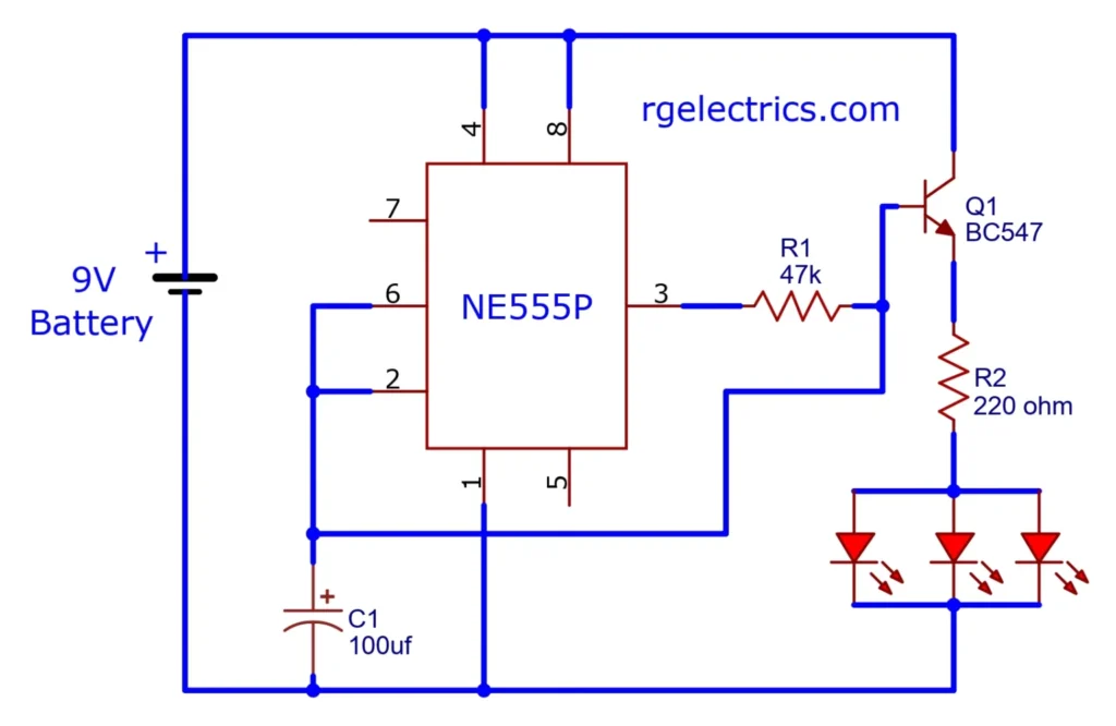
Circuit Diagram
Circuit Explanation:
This fading LED circuit uses an NE555 timer in astable mode and a BC547 transistor for current amplification. A 47kΩ resistor controls the charging rate of a 100µF capacitor, which determines the LED’s fade timing. The capacitor charges and discharges, modulating the brightness of the LED. A 220Ω resistor limits the current through the LED to prevent damage. The BC547 transistor drives the LED with sufficient current from the NE555’s output. As the capacitor charges, the LED brightens, and as it discharges, the LED dims, creating a smooth fading effect.
#7 NE555 LED Flip Flop Circuit
Introduction:
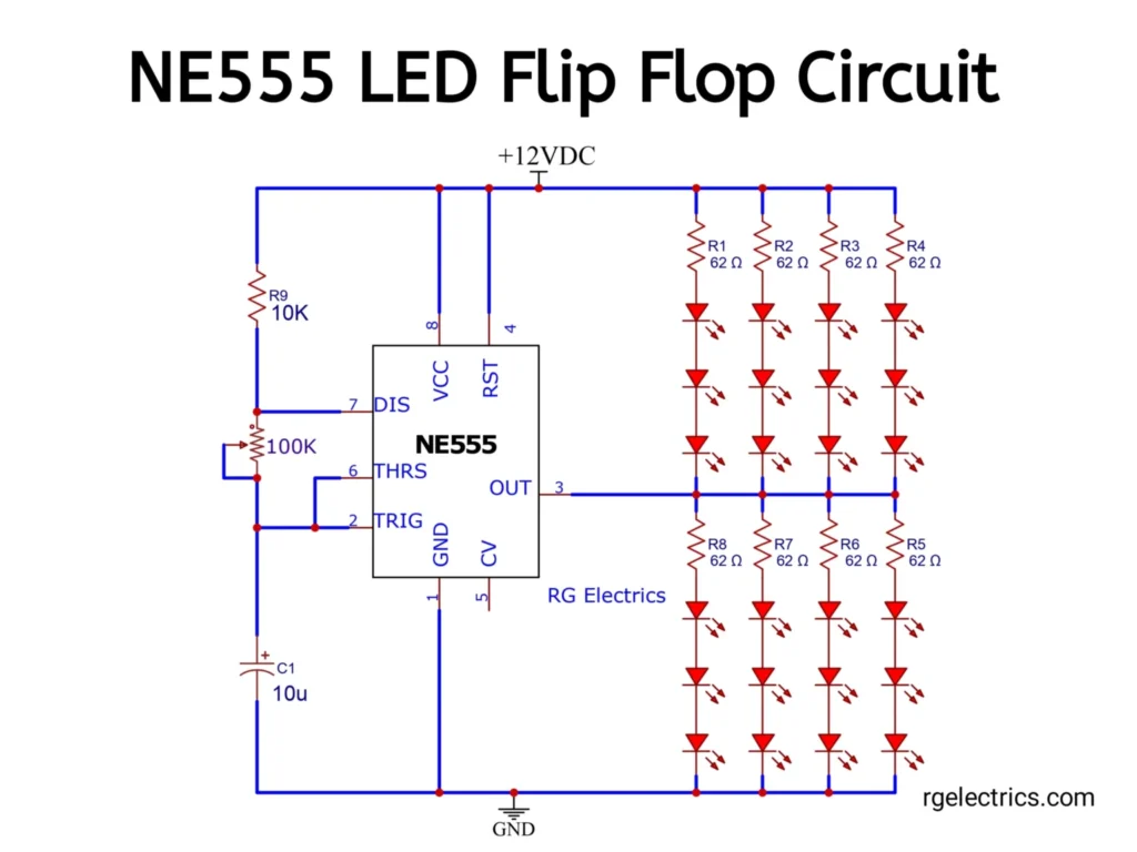
The NE555 LED flip-flop circuit is a simple yet effective electronic project that demonstrates the use of the NE555 timer integrated circuit in astable mode. In this configuration, the NE555 generates a continuous square wave signal, which causes two sets of LEDs to alternately blink, creating a “flip-flop” effect. The circuit is powered by a 12V DC supply, with resistors limiting the current to protect both the LEDs and the NE555 chip. A capacitor and resistors connected to the NE555 determine the timing of the LED blinking, allowing for the adjustment of the flashing speed.
This basic circuit is widely used in electronics projects and education because it is easy to build and helps illustrate key concepts such as oscillation, timing, and LED control. The NE555’s reliability and versatility make it a favorite component in many DIY electronics applications.
Components Need:
| S.No | Components | Value | Qty. |
|---|---|---|---|
| 1. | Time IC | NE555 | 1 |
| 2. | Resistor | 82K, 62 ohm | 1,8 |
| 3. | Variable Resistor | 100K | 1 |
| 4. | Capacitor | 10uf | 1 |
| 5. | LED | – | 24 |
| 6. | Power Supply | 12V | – |
Circuit Diagram
Working Explaination:
The NE555 LED flip-flop circuit works by generating a continuous square wave in astable mode. The NE555 timer produces alternating high and low pulses at its output (pin 3), controlled by the timing resistor (100kΩ) and the capacitor (10μF), which define the frequency of oscillation. When the output goes high, current flows through resistors R1-R4, lighting up the first set of LEDs. When the output switches to low, current flows through resistors R5-R8, illuminating the second set of LEDs. This results in an alternating blinking effect between the two LED arrays.
The 62Ω resistors limit the current to protect the LEDs from excessive current flow. The 10kΩ resistor connected to pin 7 helps discharge the capacitor, resetting the cycle. As the output continually oscillates, the LEDs blink in an alternating fashion, creating the flip-flop effect. The 12V DC power supply provides the required voltage for the operation of the entire circuit, ensuring the proper switching of the NE555 and sufficient current for the LEDs.
#8 Simple BC547 LED Flip Flop Circuit
Introduction
The BC547 LED flip-flop circuit is a fundamental electronics project often used to demonstrate the principles of switching, oscillation, and basic transistor operation. This simple but effective circuit forms the basis for understanding how transistors can be used to create an alternating pattern of on-off states, known as a flip-flop. Flip-flop circuits are used in a wide variety of applications, from basic timing circuits to more complex digital systems.
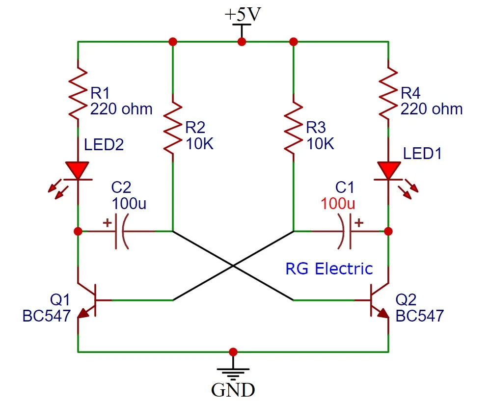
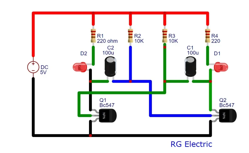
At its core, a flip-flop is a bistable multivibrator, meaning it has two stable states. In the case of the LED flip-flop circuit, the two states are represented by two LEDs, which alternately turn on and off in a repetitive sequence. The BC547 transistor, a common NPN transistor, is used in this circuit to control the flow of current and enable the switching action. The BC547 LED flip-flop circuit is a simple multivibrator circuit that uses two BC547 NPN transistors to switch two LEDs on and off alternately. This basic flip-flop configuration is commonly known as an unstable multivibrator, where both states are unstable, and it constantly flips between them.
Components Details
| S.No | Components | Value | Qty. |
|---|---|---|---|
| 1. | Transistor | BC547 | 2 |
| 2. | Resistor | 220 ohm, 10K | 2, 2 |
| 3. | Capacitor | 100uf | 2 |
| 4. | LED | RED, Blue | 1, 1 |
| 5. | DC Supply | 5V | – |
Circuit Diagram
Working Explaination
The BC547 LED flip-flop circuit works by alternately switching two transistors on and off, causing two LEDs to blink in a repeating sequence. Here’s a step-by-step explanation of how the circuit operates:
- Initial Power-On: When power is first applied, one transistor (either Q1 or Q2) turns on slightly faster than the other due to minor differences in component values.
- First Transistor Turns ON: Suppose Q1 turns on first. When Q1 is ON, current flows from the collector to the emitter of Q1, lighting up LED1. The capacitor connected between Q1’s collector and Q2’s base starts charging.
- Capacitor Charging: The capacitor connected to Q1 (C1) gradually charges through the resistor connected between Q2’s collector and Q1’s base. Once the capacitor is sufficiently charged, it applies a voltage to Q2’s base, turning Q2 ON.
- Q2 Turns ON, Q1 Turns OFF: When Q2 turns on, it causes Q1 to turn off. Now, current flows through Q2, lighting up LED2 and turning off LED1. Similarly, the capacitor connected to Q2 (C2) begins charging.
- Alternating Behavior: This process repeats continuously. As each capacitor charges and discharges, it alternates the state of the transistors. One LED turns on while the other turns off, and they keep switching back and forth in a flip-flop pattern.
- Oscillation: The switching is controlled by the charge and discharge of the capacitors, creating a blinking effect with the two LEDs turning on and off alternately.
This continuous oscillation is what makes the circuit an astable multivibrator. The frequency of blinking depends on the values of the capacitors and resistors used in the circuit.
#9 Simple Music Reactive LED Light Circuit
Introduction:
The Music Reactive LED Circuit is a simple and engaging way to visually represent sound, often used in sound-responsive decorations, DIY electronics, and audio visualizers. This circuit uses a microphone to detect sound, amplifies the audio signal using transistors, and drives an array of LEDs that light up in sync with the rhythm of the music. The circuit is ideal for beginners in electronics, as it combines fundamental components like transistors, resistors, capacitors, and LEDs to create an interactive output.
Component Details:
| S.No | Components | Value | Qty. |
|---|---|---|---|
| 1. | Transistor | BC547, C1815 | 1, 1 |
| 2. | Capacitor | 1uf/25V | 1 |
| 3. | Resistor | 1M, 100K, 5.6K | 1, 1, 1 |
| 4. | Microphone | – | 1 |
| 5. | LED | Red, Green, Blue | 1, 1, 1 |
| 6. | Battery | 9V | 1 |
Circuit Diagram

Working Explaination:
- Microphone (MIC):
The microphone is an essential input component that converts sound waves into a small electrical signal. The microphone is connected to the base of transistor Q2, which amplifies this weak signal. - Transistors (Q1 – BC547 and Q2 – C1815):
Both Q1 and Q2 are NPN transistors that serve as amplifiers. Q2 (C1815) receives the low-level signal from the microphone and provides the first stage of amplification. The amplified signal is then passed to Q1 (BC547), which further boosts the signal to a level sufficient to drive the LEDs. These transistors essentially act as signal amplifiers, making weak audio signals strong enough to trigger visual feedback from the LEDs. - Capacitor (C1 – 1uF):
The capacitor serves as a coupling element, allowing only the AC component of the signal (which corresponds to the sound) to pass while blocking any unwanted DC components. This ensures that only variations in the sound intensity are used to drive the LEDs, preventing unwanted steady lighting. - Resistors (R1, R3, R4):
- R1 (1MΩ): This resistor limits the current to the microphone, protecting it from being overloaded by excessive current.
- R3 (100KΩ) and R4 (5.6KΩ): These resistors are part of the biasing network for the transistors. They ensure the transistors are properly biased for amplification, ensuring the circuit responds well to audio signals.
- LED Array: The LEDs are connected in multiple branches, with each LED lighting up in response to the amplified signal from the transistors. The louder the sound, the greater the voltage across the LEDs, causing more LEDs to light up. The different colored LEDs (red, green, blue) create a visual representation of the audio intensity.
- Power Supply (9V Battery):
The circuit is powered by a 9V battery, providing the necessary voltage for both the amplification stage and the LED lighting. The positive terminal of the battery is connected to the LED circuit, and the negative terminal completes the circuit by connecting back to the microphone and transistor stage.
How It Works:
When sound waves hit the microphone, it generates a small electrical signal proportional to the sound’s intensity. This signal is then amplified in two stages: first by Q2, then by Q1. The amplified signal drives the LEDs, causing them to blink or glow in response to the sound. The circuit responds to varying audio levels, with louder sounds lighting up more LEDs or causing them to flash more brightly.
This music-reactive LED circuit is simple but provides a captivating visual effect, making it popular in music-themed projects and light displays.
#10 Simple Audio Amplifier Circuit using IRFZ44n

Introduction:
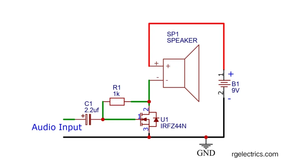
This is a basic audio amplifier circuit that amplifies low-power audio signals to drive a speaker using an IRFZ44N MOSFET. MOSFETs (Metal Oxide Semiconductor Field-Effect Transistors) are popular in amplifier designs because of their high efficiency, high input impedance, and fast switching speed. In this circuit, the MOSFET operates in the linear region, allowing it to amplify the incoming audio signal effectively. The simplicity of the design makes it suitable for low-power audio applications.
this MOSFET audio amplifier circuit using the IRFZ44N MOSFET efficiently amplifies low-power audio signals, making it ideal for basic DIY audio applications. It demonstrates the principles of signal amplification with minimal components, showcasing the use of MOSFETs in audio electronics due to their high efficiency and fast switching capabilities.
This circuit is often used in small speaker systems and educational projects, providing a straightforward approach to amplifying audio signals for low-power devices.
Components Required:
| S.No | Components | Details |
|---|---|---|
| 1. | IRFZ44N MOSFET (U1) | Acts as the main amplifying element. |
| 2. | Speaker (SP1) | Converts the amplified audio signal into sound. |
| 3. | Capacitor (C1, 2.2 µF) | Used for coupling the audio signal into the gate of the MOSFET. |
| 4. | Resistor (R1, 1kΩ) | Provides stability and helps in proper biasing of the MOSFET. |
| 5. | Power Supply (B1, 9V Battery) | Powers the circuit and provides current to the MOSFET and speaker. |
| 6. | Audio Input | Provides the audio signal to be amplified. |
Circuit Diagram
Working Explanation:
The working of this circuit can be broken down into a few simple steps:
1. Audio Signal Input:
The audio signal, typically a small AC signal, is provided as an input. This signal is too weak to directly drive the speaker, so it must be amplified.
2. Coupling Capacitor (C1):
The input audio signal passes through the capacitor C1 (2.2 µF). This capacitor serves as a coupling capacitor, meaning it blocks any DC component from the audio input, allowing only the AC component (audio signal) to pass through. This is essential because MOSFETs should ideally only receive AC signals on their gate when used for audio amplification.
3. MOSFET Operation:
The AC signal reaches the gate of the IRFZ44N MOSFET. The MOSFET is an N-channel MOSFET, and in this configuration, it works as a common-source amplifier. Here’s how it functions:
- The source (pin 3) of the MOSFET is connected to ground (GND).
- The drain (pin 2) is connected to the speaker and the power supply.
- The gate (pin 1) is where the audio signal enters.
The gate of the MOSFET has a very high input impedance, which means it doesn’t draw much current from the input signal, making it an efficient amplifier. The MOSFET amplifies the small input voltage variations (from the audio signal) by controlling the current flow between the drain and source. As the gate voltage increases due to the input signal, the MOSFET allows more current to flow through the speaker, thus amplifying the sound.
4. Speaker (SP1):
The amplified signal at the drain of the MOSFET is sent to the speaker. The speaker converts the varying current (which corresponds to the amplified audio signal) into sound. The higher the input audio signal, the more current flows through the speaker, producing louder sound.
5. Resistor (R1):
The resistor R1 (1kΩ) is connected between the gate of the MOSFET and ground. It provides a discharge path for the gate and stabilizes the MOSFET by ensuring that any residual charge on the gate gets removed when no signal is applied. Without this resistor, the MOSFET might remain partially “on” even after the audio signal stops, which could lead to distortion or unwanted noise.
6. Power Supply (9V Battery):
The circuit is powered by a 9V battery. The positive terminal of the battery is connected to the speaker and MOSFET drain, while the negative terminal is grounded. The battery provides the necessary current for the MOSFET to amplify the audio signal and drive the speaker.