

Table of Contents
Introduction:
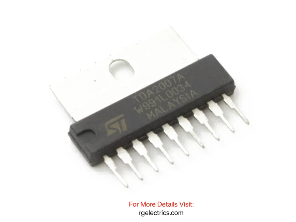
The TDA2007A is a Class AB dual audio power amplifier designed for stereo applications in audio systems such as music centers, TV receivers, and portable radios. Manufactured by STMicroelectronics, this IC is housed in a 9-pin Single In-Line Package (SIP9) and is optimized for delivering 6W per channel with low distortion and high efficiency.
Operating with a supply voltage range of 8V to 24V, the TDA2007A features high output power, high current capability, and built-in protections such as AC short circuit protection and thermal overload protection, ensuring reliability in various applications. It supports a closed-loop gain of 36dB, making it suitable for high-fidelity audio amplification.
The IC can be configured in stereo or bridge mode, where it can output up to 12W in a single-channel setup. Due to its low external component requirement, the TDA2007A is widely used in compact audio amplifier designs for consumer electronics.
Component Details:
| S.no | Components | Value | Qty. |
|---|---|---|---|
| 1. | Audio IC | TDA2007A | 1 |
| 2. | Resistor | 1KΩ, 18Ω, 1Ω | 1,1,1 |
| 3. | Capacitor | 100uf,22uf,2.2uf, 220uf,2200uf,0.1uf | 1,1,2,2,2,2 |
| 4. | Speaker | 4Ω-8Ω | 2 |
| 5. | DC Power | 8 – 24V | 1 |
| 6. | Audio Input | – | – |
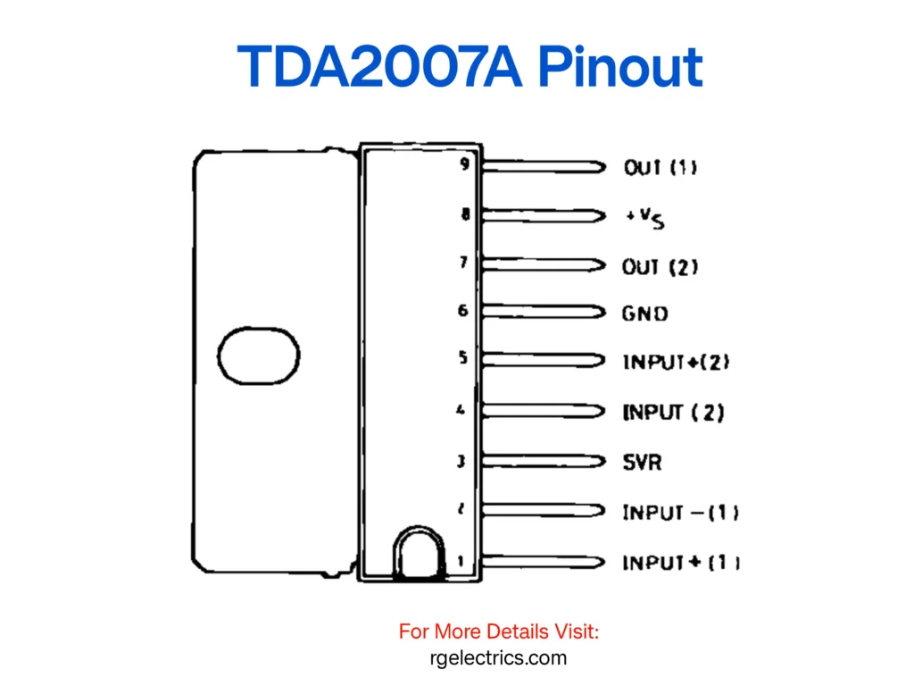
Pinout of TDA2007A:
Schematic
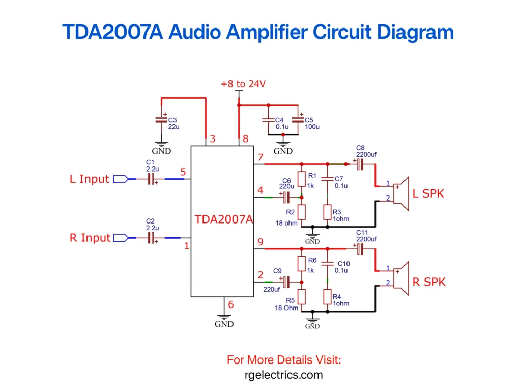
Explanation of the TDA2007A Audio Amplifier Circuit
This circuit is a stereo audio amplifier based on the TDA2007A IC, which is a dual power amplifier designed for driving speakers in audio applications. It can operate with a voltage supply between 8V to 24V and is ideal for low to medium power audio amplification.
Main Sections of the Circuit:
- Power Supply Section:
- The amplifier is powered by a single DC voltage supply ranging from +8V to +24V.
- Capacitors C3 (22uF), C4 (0.1uF), and C5 (100uF) help stabilize the power supply, filter noise, and prevent voltage fluctuations.
- Input Section:
- Left Input (L Input) and Right Input (R Input) are the two audio signal inputs.
- Capacitors C1 (2.2uF) and C2 (2.2uF) block DC components and allow AC (audio) signals to pass.
- These capacitors prevent distortion and protect the amplifier from unwanted DC signals.
- TDA2007A Amplification Section:
- The TDA2007A IC has two independent amplifier channels (one for each speaker).
- Pin 5 and Pin 1 receive the left and right audio inputs, respectively.
- Pin 3 and Pin 8 are connected to the positive power supply.
- Gain and Feedback Network:
- Capacitors C6 (220uF) and C9 (220uF), along with resistors R2 (18Ω) and R5 (18Ω), set the gain of the amplifier.
- Resistors R1 (1kΩ), R6 (1kΩ), R3 (1Ω), and R4 (1Ω) form a feedback loop, stabilizing the amplification and improving sound quality.
- Capacitors C7 (0.1uF) and C10 (0.1uF) help to remove high-frequency noise and enhance stability.
- Output Section:
- Capacitors C8 (2200uF) and C11 (2200uF) are used for DC blocking, ensuring only the amplified AC signal reaches the speakers.
- The left and right speaker outputs (L SPK and R SPK) are connected at the output stage.
- Grounding:
- The GND (ground) connections at Pin 6 and other points ensure proper reference voltage and stability.
- Proper grounding is essential to prevent noise and interference.
Working of the Circuit:
- The audio signals from the left and right channels are fed into Pin 5 and Pin 1 of the TDA2007A IC.
- These signals are amplified through the internal operational amplifiers inside the TDA2007A.
- The gain is controlled using the external capacitors and resistors in the feedback network.
- The amplified signals are passed through DC blocking capacitors (C8 and C11) to the left and right speakers (L SPK & R SPK).
- The output speakers reproduce the amplified audio signal.
Applications:
- Home audio systems
- Portable speaker systems
- TV sound amplifiers
- DIY audio amplifier projects


