

Table of Contents
Introduction:
The TDA2006 audio amplifier circuit is a versatile, low- to medium-power amplifier used in various audio systems. Capable of delivering up to 12W of output power, it is ideal for driving speakers in home audio setups, powered speakers, or DIY projects. The dual power supply ensures high efficiency and linearity, providing clear audio amplification across a wide frequency range. The use of protective components, such as diodes, makes the circuit robust, while capacitors and resistors control gain and stability, ensuring high-quality audio output.
The TDA2006 operates with a dual power supply, with +12V and -12V as shown in the schematic. It is designed to amplify audio signals and drive a speaker, converting a weak audio input signal into a more powerful output signal that can drive a loudspeaker.
Component List:
| Component | Value | Description |
|---|---|---|
| TDA2006 | – | Audio amplifier IC |
| C1 | 100 nF | Decoupling capacitor |
| C2 | 22 µF | Capacitor in the feedback loop |
| C3 | 0.22 µF | Output coupling capacitor |
| C4 | 100 nF | Power supply decoupling capacitor |
| C5 | 1 µF | Input coupling capacitor |
| R1 | 22K | Resistor in the feedback network |
| R2 | 680 Ω | Resistor for gain control |
| R3 | 1 Ω | Speaker current limiting resistor |
| R5 | 22K | Feedback resistor |
| D1, D2 | 1N4007 | Reverse voltage protection diodes |
| SP1 | – | Speaker |
TDA2006 Pinout and Details:
The TDA2006 is a monolithic integrated circuit designed for audio applications, primarily functioning as a low- to medium-power audio amplifier. it is commonly used in home audio systems, car audio, and powered speakers due to its simple design and ability to provide a high output power of up to 12W. The TDA2006 is favored for its versatility, low distortion, and reliability.
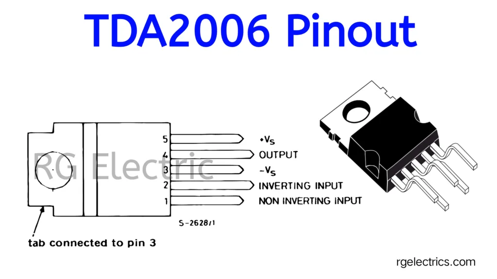
TDA2006 Pinout:
- Pin 1 (Non-Inverting Input):
- This is the positive input terminal where the input signal is applied.
- Pin 2 (Inverting Input):
- This is the negative input terminal, typically connected to the feedback loop in the amplifier circuit.
- Pin 3 (-Vs, Negative Supply):
- The negative power supply is connected here (e.g., -12V in dual supply configurations).
- The metal tab of the IC is also internally connected to this pin.
- Pin 4 (Output):
- This is the output terminal where the amplified audio signal is provided to the speaker or load.
- Pin 5 (+Vs, Positive Supply):
- The positive power supply (e.g., +12V) is connected here to power the IC.
Note:
- The tab of the IC is connected to pin 3 (the negative supply), so ensure proper insulation or heat sinking when mounting the IC to avoid accidental grounding issues.
Key Features of TDA2006:
- Power Output: Can deliver up to 12W into a 4Ω load at ±12V.
- Low Harmonic Distortion: Ensures clear audio reproduction with minimal distortion.
- Wide Operating Voltage Range: Works efficiently with a supply range of ±6V to ±18V.
- Short-circuit protection: Built-in protection to safeguard against speaker damage due to accidental short circuits.
- Thermal Shutdown: Protects the IC from overheating, ensuring durability.
- Low Noise: Provides low noise amplification, ideal for high-fidelity audio applications.
Circuit Diagram:
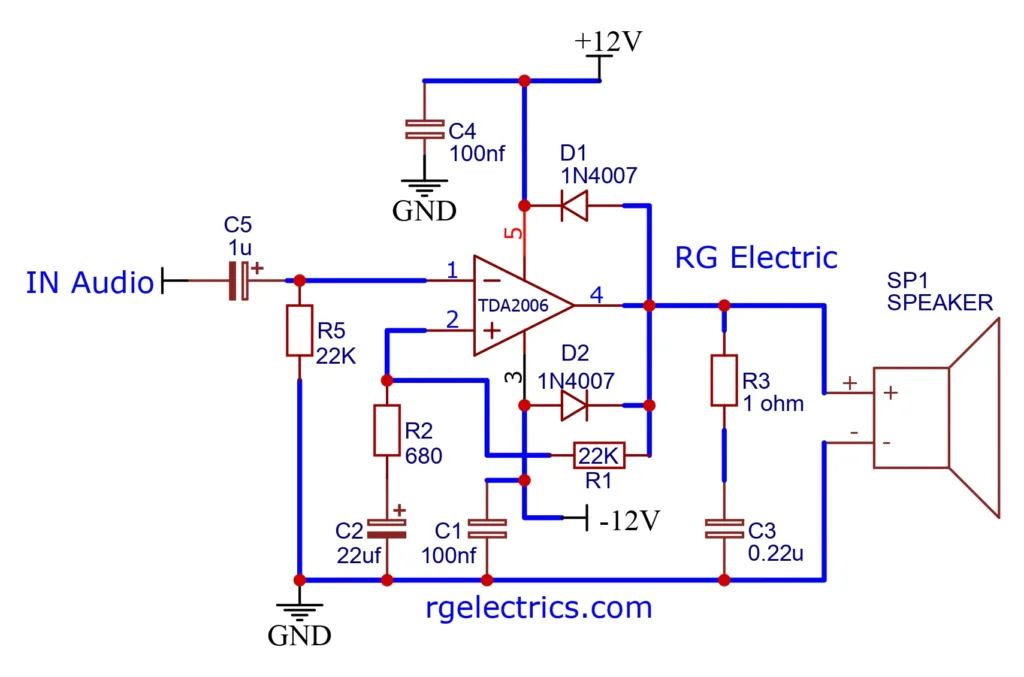
Working Explaination:
Audio Input (IN Audio): The audio signal enters through the capacitor C5 (1 µF), which acts as a coupling capacitor, allowing only AC signals (audio signals) to pass and blocking any DC component that might be harmful to the circuit.
TDA2006 IC: The core of the circuit is the TDA2006 operational amplifier, which amplifies the audio signal. Pins 1 and 2 are used as the input terminals, where the positive feedback is provided to the inverting input (pin 2) and the non-inverting input (pin 1) receives the input signal.
Power Supply: The circuit is powered by a dual supply (+12V and -12V) connected to pins 5 and 3 of the IC, respectively. This allows for symmetric operation, meaning the IC can handle both positive and negative portions of the audio signal effectively.
Feedback Loop: A feedback network is established using R5 (22K) and R2 (680Ω) to control the gain of the amplifier. C2 (22 µF) is used in the feedback loop to stabilize and improve the frequency response.
Diodes (D1 and D2): 1N4007 diodes are connected in parallel to protect the circuit from any reverse voltage that could damage the amplifier.
Speaker Output: The amplified signal is sent to the speaker via C3 (0.22 µF), which blocks any remaining DC component, ensuring that the speaker only receives the amplified AC signal. R3 (1Ω) is used to limit the current flowing to the speaker.
Explanation of Key Components:
- TDA2006: A power amplifier IC that can drive speakers in low- to mid-power audio systems.
- Capacitors (C1, C2, C3, C4, C5): These capacitors are used for various purposes like coupling, decoupling, and frequency stabilization.
- Resistors (R1, R2, R3, R5): These resistors are used to set the gain of the amplifier and limit the current in the circuit.
- Diodes (D1, D2): These protect the circuit from reverse polarity and high voltages.
Applications:
Here are some common applications of the TDA2006:
- Home Audio Amplifiers
- Car Audio Systems
- Powered Speakers
- Subwoofer Drivers
- TV Audio Systems
- Portable Audio Devices
- PA Systems (Public Address)
- DIY Audio Projects
- Guitar and Instrument Amplifiers
- Audio Signal Amplification for Radios


