Table of Contents
Introduction:
The TDA2005 is a high-performance dual power amplifier IC designed for audio applications, particularly in car radio systems and home audio amplifiers. Manufactured by STMicroelectronics, this IC is capable of delivering up to 20 watts of output power per channel when configured in bridge-tied load (BTL) mode, making it ideal for low- to medium-power stereo audio systems.
The TDA2005 is popular for its simplicity and efficiency, requiring only a few external components to operate, which makes it a cost-effective solution for audio enthusiasts and professionals. With a wide operating voltage range of 9V to 18V, it can be powered by typical automotive electrical systems or standard power supplies.
This IC is well-regarded for its reliability, offering built-in protection features like thermal shutdown, short-circuit protection, and protection against voltage overloads. These features help prevent damage and ensure long-term stable operation.
The TDA2005 provides good sound quality with minimal distortion, making it suitable for applications that demand clear and powerful audio output. Due to its versatility and ease of use, it has become a go-to choice for both DIY audio projects and commercial audio amplifier designs.
Components Required:
| S.No | Components | Value | Qty. |
|---|---|---|---|
| 1. | IC | TDA2005 | 1 |
| 2. | Capacitor | 2200uf, 100uf, 220uf, 2.2uf, 0.1uf, 10uf | 2,2,2,2,3,1 |
| 3. | Resistor | 120K, 1.2K, 33R, 1R | 1, 2, 2, 2 |
| 4. | Speaker | 8 ohm | 2 |
| 5. | Audio Input | – | – |
| 6. | Power Supply | 9V-18V | – |
Pinout of TDA2005 IC :

- Pin 1 (INPUT+1): Positive input for the first amplifier (Channel 1).
- Pin 2 (INPUT-1): Negative input for the first amplifier (Channel 1).
- Pin 3 (SVRR): Supply voltage rejection ratio (used to stabilize the power supply and reduce noise).
- Pin 4 (INPUT-2): Negative input for the second amplifier (Channel 2).
- Pin 5 (INPUT+2): Positive input for the second amplifier (Channel 2).
- Pin 6 (GND): Ground connection.
- Pin 7 (BOOTSTRAP 2): Bootstrap pin for the second amplifier (Channel 2), which enhances the high-frequency response.
- Pin 8 (OUTPUT 2): Output for the second amplifier (Channel 2).
- Pin 9 (Vs): Power supply pin (9V to 18V DC).
- Pin 10 (OUTPUT 1): Output for the first amplifier (Channel 1).
- Pin 11 (BOOTSTRAP 1): Bootstrap pin for the first amplifier (Channel 1).
Additional Notes:
- The tab (heatsink) is internally connected to pin 6 (GND), which helps in heat dissipation and grounding.
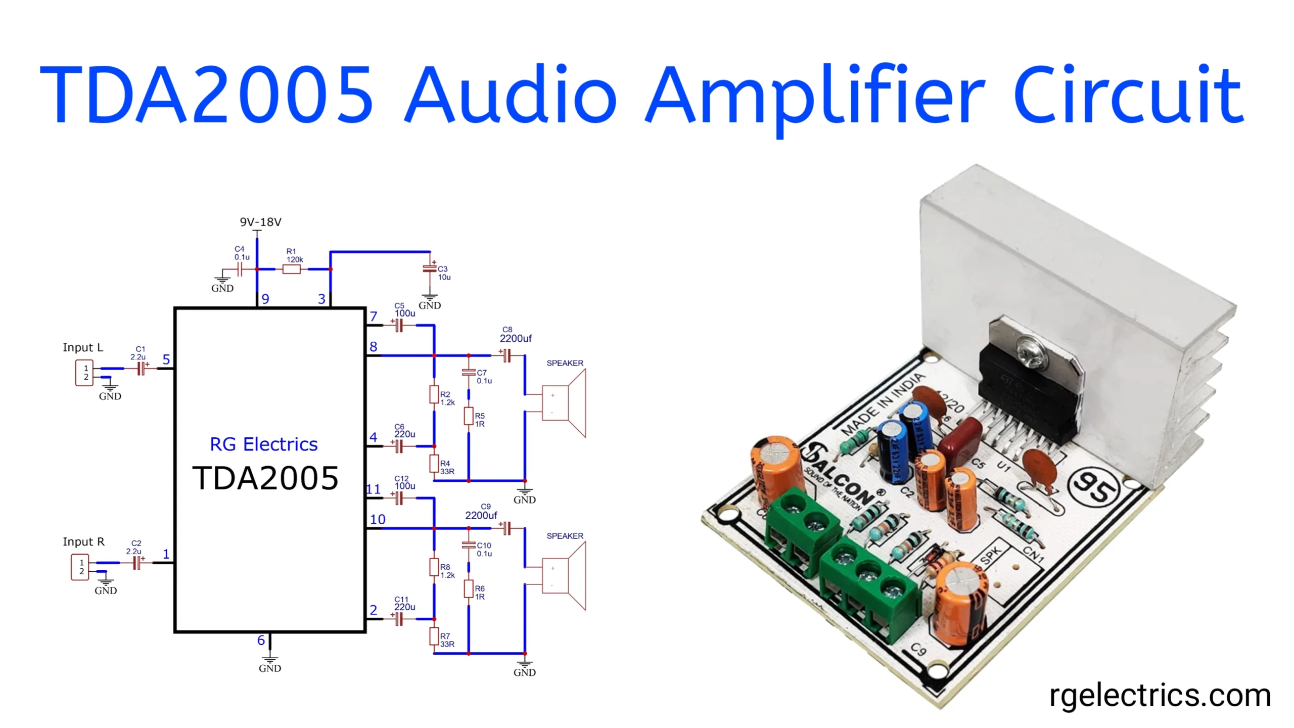
Circuit Diagram:

Circuit Working:
The TDA2005 audio amplifier circuit consists of several components working together to amplify stereo audio signals. Here’s an explanation of the key parts and their functions in a typical stereo amplifier circuit based on the TDA2005 IC:
Key Components and their Functions:
- Power Supply (Pin 9 – Vs):
- The TDA2005 requires a DC power supply ranging from 9V to 18V. In the circuit, a capacitor (C3, typically 10µF) is connected to smooth out the input voltage and filter any noise from the power supply. Capacitor C4 (0.1µF) is used for decoupling to prevent oscillations or disturbances caused by sudden changes in voltage.
- Input Section (Pins 1 and 2, Pins 4 and 5):
- The audio signals are fed into the INPUT+ and INPUT- pins of the IC (pins 1 and 2 for channel 1, and pins 4 and 5 for channel 2).
- Coupling capacitors C1 and C2 (2.2µF) are used at the input stage to block any DC voltage from reaching the input of the amplifier while allowing the AC audio signal to pass through. These capacitors ensure only the audio frequencies are amplified.
- Feedback and Bootstrap Capacitors (Pins 7 and 11 for Bootstrap):
- Bootstrap capacitors C5, C12, C6, and C11 are used to enhance the high-frequency performance of the amplifier by maintaining a consistent voltage swing at the output.
- These capacitors also help improve the amplifier’s efficiency by providing better voltage regulation across the internal stages of the IC.
- Output Section (Pins 8 and 10):
- The amplified audio signals are output through Pin 8 for channel 2 and Pin 10 for channel 1.
- Output capacitors C8 and C9 (both 2200µF) are used to block DC components and ensure only the AC audio signal reaches the speakers.
- Resistors R2, R5, R8, and R6 (typically 1Ω or 1.2kΩ) are placed for stability and to control feedback, ensuring proper operation at high power levels without oscillation.
- Speaker Connection:
- The output from the TDA2005 is connected to the speakers through capacitors, ensuring clear audio output. The speakers are grounded on the other side to complete the circuit.
- Ground (Pin 6):
- Pin 6 of the IC is connected to ground to provide a common reference voltage and complete the circuit.
- Additional Components:
- Components such as resistors (R1, R2, R3, etc.) are used for biasing and feedback to ensure stable and optimal performance of the amplifier.
- The circuit may also include bypass capacitors and bootstrap capacitors to enhance the frequency response and ensure the amplifier works efficiently without distortion at higher frequencies.
Circuit Operation:
- Input Signal: The audio signals are input into the amplifier circuit through capacitors (C1, C2), which block DC components and allow AC audio signals to pass.
- Amplification: The TDA2005 IC amplifies the input audio signals using its internal amplifier circuitry. The gain of the amplifier is controlled by external feedback components (resistors and capacitors).
- Output Signal: The amplified audio signals are passed through output capacitors (C8, C9) to remove any DC offset before being sent to the speakers.
Protection and Safety:
The TDA2005 has built-in protection features, including:
- Thermal Shutdown: Prevents overheating by shutting down the IC if it reaches a certain temperature.
- Short-Circuit Protection: Protects the IC from damage in case of a short circuit at the output.
- Overload Protection: Ensures the IC doesn’t get damaged due to excessive voltage or current.
Summary:
The TDA2005 audio amplifier circuit amplifies stereo audio signals and drives two separate speakers. It operates efficiently with a 9V–18V power supply, and the external components ensure the IC delivers good sound quality with minimal distortion. The circuit is simple to build and commonly used in car audio systems or home stereo setups. The IC’s internal protection mechanisms make it a robust and reliable choice for audio amplification projects.
Applications and Uses:
- Car radio amplifiers
- Portable speaker systems
- Home stereo systems
- DIY audio amplifier projects

