Table of Contents
Introduction:
The TDA2004 is a dual bridge amplifier IC designed for car radio and audio amplifier applications, delivering up to 10W per channel. It is particularly suitable for driving low-impedance speakers and provides high power output in a compact package, making it ideal for both automotive and home audio systems.
The TDA2004 stereo amplifier circuit is a simple and effective way to amplify left and right audio channels for stereo sound. In this circuit, the TDA2004 operates in bridge mode, using two amplifiers for each channel to increase power output. This configuration ensures efficient power delivery to the speakers, offering improved audio quality and higher volume output.
This circuit includes essential components such as input coupling capacitors, feedback resistors, and output capacitors to ensure stable, clear sound amplification, while also blocking unwanted DC signals and minimizing noise. The power supply is flexible, operating from 9V to 18V, making it versatile for various setups.
Components Required:
| S.No | Components | Value | Qty. |
|---|---|---|---|
| 1. | IC | TDA2004 | 1 |
| 2. | Capacitor | 2200uf, 100uf, 220uf, 2.2uf, 0.1uf, 10uf | 2,2,2,2,3,1 |
| 3. | Resistor | 120K, 1.2K, 33R, 1R | 1, 2, 2, 2 |
| 4. | Speaker | 8 ohm | 2 |
| 5. | Audio Input | – | – |
| 6. | Power Supply | 9V-18V | – |
Pinout of TDA2004:

- Pin 1 (Input + (1)): Positive input for channel 1 (left channel).
- Pin 2 (Input – (1)): Negative input for channel 1.
- Pin 3 (SVRR): Supply voltage rejection ratio pin, used for noise filtering and power supply rejection.
- Pin 4 (Input – (2)): Negative input for channel 2 (right channel).
- Pin 5 (Input + (2)): Positive input for channel 2.
- Pin 6 (GND): Ground pin, connected to the circuit ground.
- Pin 7 (Bootstrap (2)): Bootstrap pin for channel 2, used to improve the efficiency of the amplifier.
- Pin 8 (Output (2)): Output for channel 2 (right speaker).
- Pin 9 (+Vs): Positive power supply voltage input, where the supply voltage (9V-18V) is connected.
- Pin 10 (Output (1)): Output for channel 1 (left speaker).
- Pin 11 (Bootstrap (1)): Bootstrap pin for channel 1, similar to pin 7, for improving efficiency.
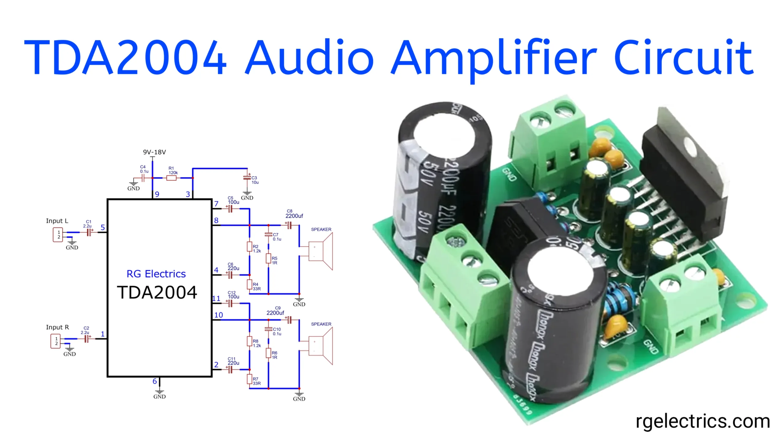
Circuit Diagram:

Working Explaination:
Let’s go through the explanation of the TDA2004 10W Stereo Audio Amplifier circuit step by step:
Power Supply:
- 9V-18V DC Input: The amplifier operates on a DC supply voltage between 9V and 18V, which is applied to pin 9. This supply powers the entire circuit.
- C4 (0.1 µF): This is a decoupling capacitor that helps to filter high-frequency noise from the power supply.
- R1 (120kΩ): This resistor is connected to pin 3, which is part of the internal biasing of the amplifier, helping set the operating point.
Input Section:
- Input L (Left Channel, pin 5): The left audio signal enters via C1 (2.2 µF), which acts as a coupling capacitor, blocking any DC component from the input and allowing only AC (audio) signals.
- Input R (Right Channel, pin 1): Similarly, the right audio signal enters through C2 (2.2 µF), which also blocks DC from the right channel’s input signal.
Amplification (Left and Right Channels):
The TDA2004 operates in bridge mode, which means each channel (left and right) uses two internal amplifiers to drive the speakers, increasing the output power.
Left Channel:
- Pin 7: This is one of the outputs for the left channel. It is connected through C5 (100 µF) and C3 (10 µF) to the speaker. The capacitor blocks DC while allowing the amplified AC (audio) signal to pass through.
- Pin 4: This is the second output for the left channel. It goes through C6 (220 µF), and together with R4 (33Ω), R2 (1.2kΩ), and R5 (1Ω), it forms a feedback network that stabilizes and controls the gain of the amplifier.
- C8 (2200 µF): This large capacitor couples the amplified signal to the speaker and blocks any DC component from reaching the speaker.
Right Channel:
- Pin 10: This is one of the outputs for the right channel. It is connected to the speaker via C11 (220 µF) and C9 (2200 µF). Similar to the left channel, it blocks DC and allows the audio signal to pass.
- Pin 11: This is the second output for the right channel. It is connected via C12 (100 µF) and interacts with the feedback network formed by R8 (1.2kΩ), R7 (33Ω), and R6 (1Ω) to stabilize the amplifier’s performance.
Feedback and Stability:
- The resistors and capacitors connected to the output and feedback loop (e.g., R2, R5, R8, R6, etc.) control the gain of each amplifier, ensuring stable and distortion-free operation. The combination of resistors (R) and capacitors (C) also defines the frequency response of the amplifier, preventing unwanted oscillations.
Grounding and Decoupling:
- Pin 6 and Pin 2: These are the ground pins for the left and right channels, respectively. They provide a common return path for the signals and the power supply.
- C7 (0.1 µF) and C10 (0.1 µF): These capacitors are placed for local decoupling near the ground to filter out any residual high-frequency noise from the power supply.
Speakers:
- The speakers are connected to the amplifier outputs via capacitors (C8 and C9). The speakers receive the amplified audio signal and convert it to sound.
Summary:
The TDA2004 is a stereo bridge amplifier IC that is used to drive two speakers with an output power of up to 10W per channel, depending on the power supply voltage and speaker impedance. This circuit filters and amplifies the audio signals for both the left and right channels and sends the amplified signals to the connected speakers. The various capacitors and resistors ensure proper signal coupling, decoupling, and feedback, providing stable amplification.
Applications:
- Car Audio Systems
- Portable Stereo Systems
- Home Audio Amplifiers
- DIY Audio Projects
- Small Speaker Systems
- Battery-Powered Amplifiers

