Table of Contents
Introduction
In a world filled with smart devices, remote controls play a vital role in making our lives more convenient. Whether it’s a TV, AC, music system, or even home automation gadgets, most of them are operated with infrared (IR) remotes. But what happens when your remote suddenly stops working? Is it the battery? The sensor? Or is the remote itself faulty?
Instead of guessing, you can use a Remote Tester Circuit — a compact, easy-to-build electronic circuit that helps you quickly verify whether your remote control is transmitting IR signals. It’s an essential tool not just for electronics hobbyists, but also for service engineers, technicians, and DIY enthusiasts.
This article dives deep into the working, components, and step-by-step explanation of how you can build your own Remote Tester Circuit using a few simple components like a TSOP1738 IR sensor, a PNP transistor, and a couple of resistors.
Components Requried
| S.No. | Component | Value / Part Number | Description | Quantity |
|---|---|---|---|---|
| 1 | IR Receiver Module | TSOP1738 | 38kHz Infrared Receiver | 1 |
| 2 | Resistor | 47Ω | Current limiting for VS line | 1 |
| 3 | Resistor | 1kΩ | Base resistor for transistor | 2 |
| 4 | Resistor | 10kΩ | Pull-up resistor for transistor base | 1 |
| 5 | Diode | 1N4001 | General-purpose rectifier (protection diode) | 1 |
| 6 | PNP Transistor | BC558 | General-purpose PNP BJT | 1 |
| 7 | LED | Red (or any color) | Indicator LED | 1 |
| 8 | Power Supply | +5V DC | Regulated power source | 1 |
| 9 | Breadboard/PCB | – | For circuit assembly | 1 |
| 10 | Connecting Wires | – | For making connections | As required |
BC558 Pinout

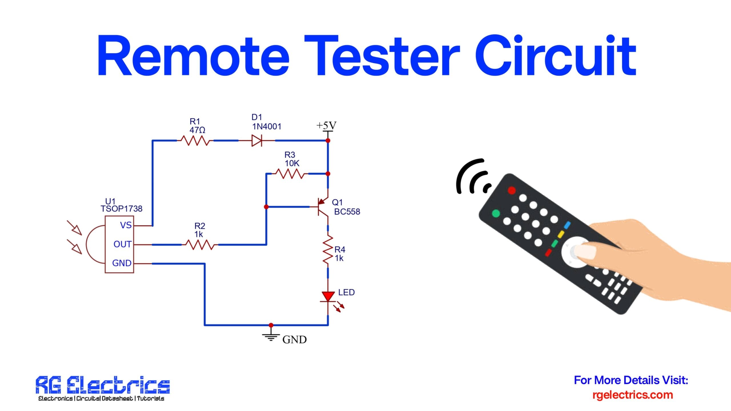
Circuit Diagram

How the Remote Tester Circuit Works
1. IR Signal Detection:
The heart of this circuit is the TSOP1738, an IR receiver module tuned to detect signals around 38kHz, which is the frequency used by most IR remotes. When the TSOP1738 receives an IR signal from a remote, its OUT pin goes LOW.
2. Transistor Operation:
The LOW signal from the TSOP1738 is passed through R2 (1kΩ) to the base of a BC558 PNP transistor (Q1). Since the transistor is PNP, a LOW signal on the base allows current to flow from the emitter to the collector.3. LED Activation:
When the transistor conducts, current flows through the R4 (1kΩ) resistor and the LED, lighting it up. This visual indication confirms that the remote control is transmitting an IR signal.
4. Diode Protection:
The 1N4001 diode (D1) is placed in series with the power line to protect the circuit from reverse polarity. This ensures that the components are safe in case the power is connected incorrectly.
Applications of the Remote Tester Circuit
- ✅ Home Troubleshooting: Test remotes for TVs, set-top boxes, air conditioners, etc.
- ✅ Electronics Labs: Great tool for beginners to learn about IR and transistors.
- ✅ Repair Shops: Quick and efficient tool for checking remote health.
- ✅ DIY Projects: Useful as a submodule in larger IR-based automation projects.
How to Build the Circuit
- Power the TSOP1738 using a regulated 5V DC power source.
- Connect the OUT pin of the TSOP1738 to the base of the BC558 transistor via the R2 resistor.
- Use R3 as a pull-up resistor to stabilize the transistor base.
- Connect the LED with R4 to the collector of the transistor and ground.
- Place a diode (D1) in the supply line for reverse polarity protection.
- Test the setup by pointing any IR remote at the sensor and pressing a button. The LED should blink.