Table of Contents
Introduction
The NE555 Buzzer Circuit is a simple yet highly useful electronic circuit that produces an audible sound using a 555 timer IC. The 555 timer is one of the most versatile ICs used in electronics for generating pulses, delays, and oscillations. In this circuit, it is configured in astable mode, meaning it continuously oscillates between high and low states to drive a buzzer or speaker. The oscillations create a frequency that is converted into sound by the speaker.
This type of buzzer circuit is commonly used in security systems, alarm circuits, doorbells, metronomes, and various audio alert systems. By modifying the resistor and capacitor values, you can adjust the tone and pitch of the buzzer to suit different applications. This project is ideal for beginners who want to explore audio electronics and timer circuits.
Components List
To construct this circuit, you will need the following components:
| Component | Specification | Quantity |
|---|---|---|
| NE555 Timer IC | – | 1 |
| Resistors | 1kΩ | 1 |
| 5.6kΩ | 1 | |
| 15kΩ | 1 | |
| Capacitors | 10µF | 2 |
| 100µF | 2 | |
| 0.01µF | 1 | |
| Speaker/Buzzer | 8Ω Speaker | 1 |
| Power Supply | 9V DC Battery | 1 |
| Miscellaneous | Connecting wires, Breadboard/PCB | – |
NE555 IC Pinout
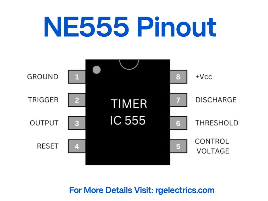
The NE555 Timer IC is an 8-pin integrated circuit commonly used for pulse generation and oscillator circuits. The pin configuration is as follows:
- GND (Ground) – Connected to the negative terminal of the power supply.
- TRIG (Trigger Input) – Starts the timing cycle when voltage drops below 1/3 of VCC.
- OUT (Output) – Provides the oscillating signal to drive the speaker.
- RESET – Active-low reset input (typically connected to VCC for normal operation).
- CTRL (Control Voltage) – Used for modifying the threshold voltage (left unconnected or grounded via a capacitor).
- THRESH (Threshold Input) – Monitors voltage levels to reset the timing cycle.
- DISCH (Discharge Pin) – Discharges the timing capacitor to reset the cycle.
- VCC (Power Supply) – Provides operating voltage (5V-15V).
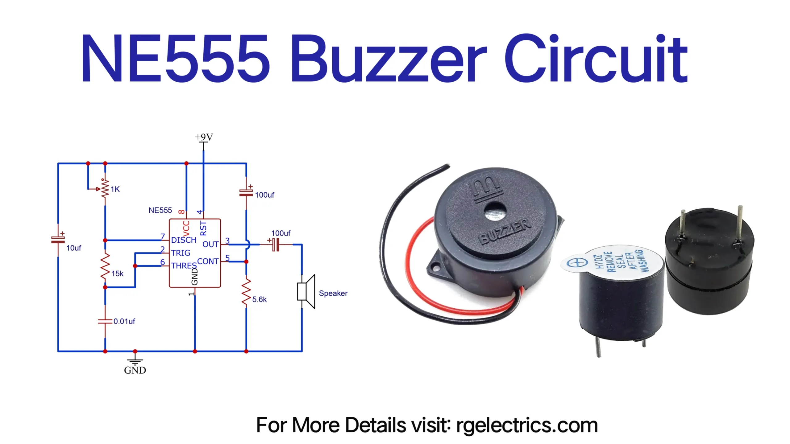
Circuit Diagram
Circuit Explanation
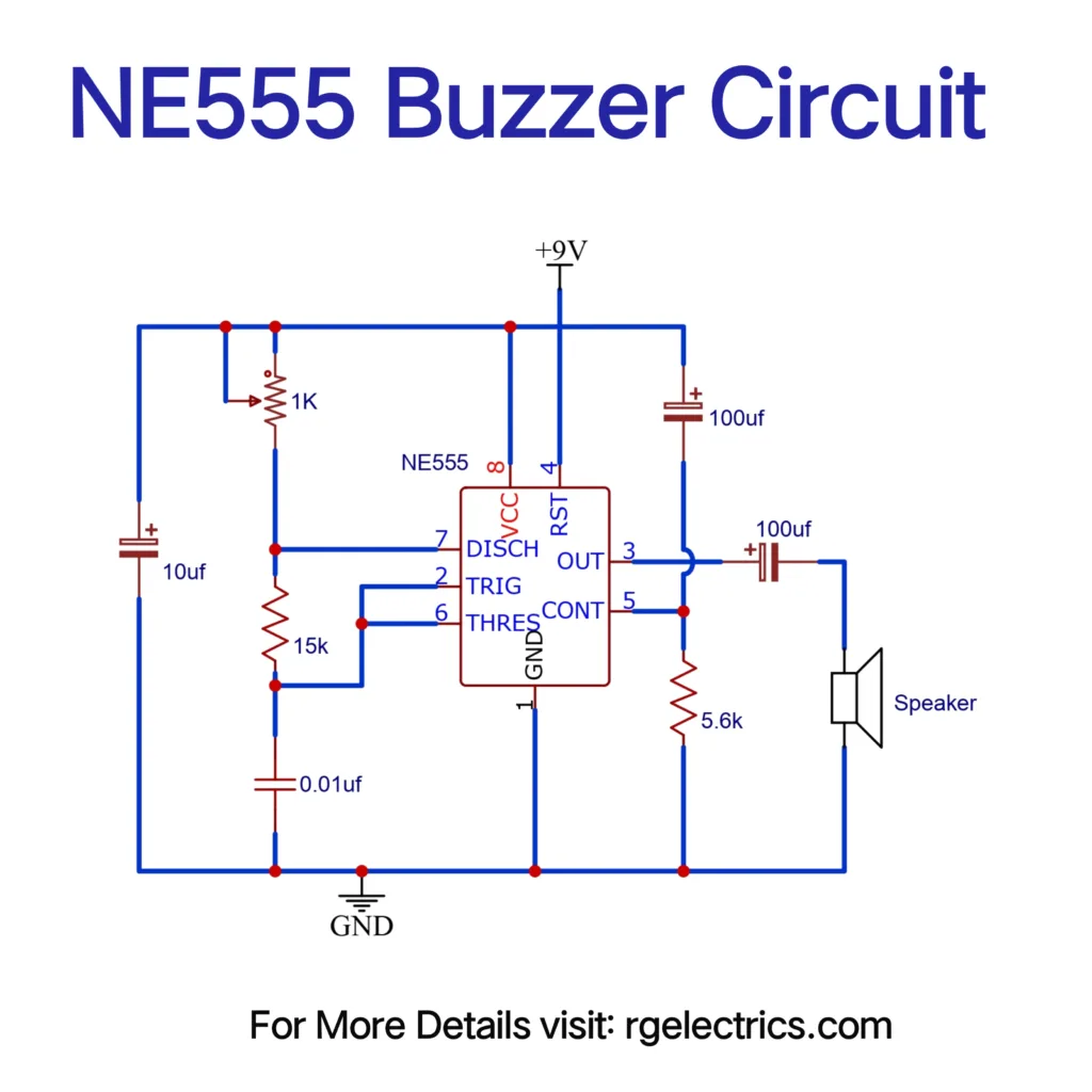
- The NE555 timer IC is configured in astable mode, which means it continuously generates square wave pulses at its output (pin 3).
- Resistors (1kΩ, 15kΩ, and 5.6kΩ) and capacitors (10µF, 100µF, 0.01µF) determine the oscillation frequency.
- The oscillating output from pin 3 is passed through a capacitor (100µF) and a resistor (5.6kΩ) to smoothen the signal and drive the speaker/buzzer.
- The speaker produces an audible tone corresponding to the frequency of the oscillations.
- The 9V battery supplies the necessary power to the circuit.
- Adjusting the resistor and capacitor values changes the frequency and pitch of the sound.
- The capacitors store and release charge periodically, ensuring stable oscillations for continuous buzzer operation.
- The output frequency is given by: F =1.44(R1+2R2)×C1
- F is the output frequency (Hz)
- R1 and R2 are resistors in ohms (Ω)
- C1 is the capacitor in farads (F)
Applications
This NE555 Buzzer Circuit has various practical applications, including:
- Alarm Systems: Used in burglar alarms, security alerts, and fire alarms to notify users of potential dangers.
- Doorbells: Can function as a simple electronic doorbell circuit for homes and offices.
- Sound Effects: Used in toys, games, and entertainment systems to generate beeping sounds.
- Warning Indicators: Employed in industrial and automotive applications to provide warning signals.
- Electronic Metronomes: Used by musicians to maintain rhythm during practice sessions.
- Time-based Reminders: Helps users keep track of time-based events using an audible notification.
- Educational Demonstrations: A great way for students and hobbyists to understand oscillator circuits and 555 timer applications.
Conclusion
The NE555 Buzzer Circuit is a straightforward and practical project for beginners and electronics enthusiasts. By adjusting the resistor and capacitor values, you can modify the sound frequency to suit different applications. Whether for alarm systems, notifications, musical effects, or experimentation, this circuit is an excellent way to learn about 555 timer-based oscillators and their role in audio signal generation. This project not only enhances technical knowledge but also provides a functional and enjoyable way to explore the world of electronics.