The LED Flasher Circuit is a simple electronic project used to make an LED blink at regular intervals. It is commonly built using a few basic components such as transistors, resistors, a capacitor, and an LED powered by a small battery. The main purpose of this circuit is to create a visual flashing effect that can be used in indicators, toys, decoration lights, and simple signaling systems. Unlike a steady glowing LED, this circuit automatically switches the LED ON and OFF repeatedly, attracting attention with its blinking pattern. It is a beginner-friendly project that helps students and hobbyists understand the basic concept of switching, timing, and capacitor charging-discharging in electronics. Due to its simplicity and low cost, it is widely used for educational and practical purposes.
Component Details
Component
Specification/Value
Quantity
Function
Transistor Q1
BC557 (PNP)
1
Acts as a switching transistor
Transistor Q2
BC547 (NPN)
1
Drives the LED ON/OFF
Resistor R1
1 MΩ
1
Controls capacitor charging time
Capacitor C1
10 µF / 16V (Electrolytic)
1
Provides timing for LED flashing
LED
5mm (Any Color)
1
Visual flashing indicator
Battery
9V DC
1
Power supply for the circuit
BC547 Pinout
Pin Number
Pin Name
Type
Function
1
Collector
Output
Current flows out; connected to load (e.g., LED, resistor)
2
Base
Control
Controls transistor switching (small current here controls large current)
3
Emitter
Ground/Return
Current flows out to ground (negative terminal)
BC557 Pinout
Pin Number
Pin Name
Type
Function
1
Collector
Output
Current flows into the transistor; connected to load
2
Base
Control
Controls transistor switching (small current here allows large current flow)
3
Emitter
Ground/Return
Current flows out to the negative side of supply
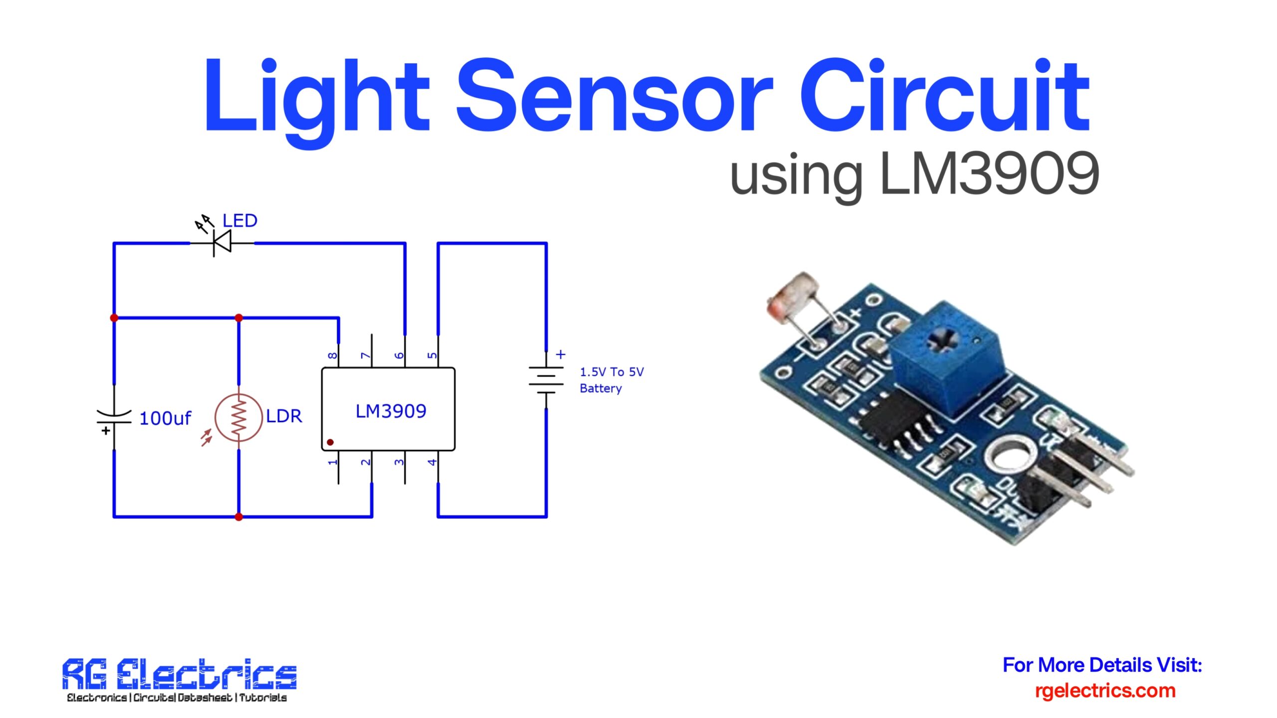
Circuit Diagram
Circuit Explain
This circuit works like an Astable Multivibrator that makes the LED flash continuously.
At the beginning (Power ON): The capacitor C1 is empty (discharged).
Charging Phase:
C1 starts charging through resistor R1.
While charging, the voltage across C1 changes the biasing of the transistors Q1 and Q2.
LED ON:
When C1 reaches a certain voltage, Q2 (NPN) turns ON.
Current flows through the LED, and it glows.
LED OFF:
After some time, C1 discharges.
When it discharges, Q2 turns OFF, cutting current through the LED, so the LED goes OFF.