Table of Contents
Introduction
The LED Dimmer Circuit using NE555 is a simple and efficient electronic project designed to control the brightness of LEDs by adjusting the voltage through pulse width modulation (PWM). This circuit provides smooth dimming without flickering and can be used with different types of LEDs or small DC lamps. The NE555 timer IC is the core component, known for its versatility, stability, and ease of use in timing and waveform generation applications. By varying the duty cycle of the output signal, the LED brightness can be increased or decreased efficiently without wasting power as heat. The circuit operates on a wide voltage range (5V to 16V), making it suitable for battery-powered systems or DC adapters. It is widely used in DIY lighting systems, automotive lighting, and decorative LED control projects where brightness adjustment is required with high reliability and simplicity.
Components Requreid
| Component Name | Symbol/Part Number | Value / Rating | Description / Function |
|---|---|---|---|
| Timer IC | NE555 | – | Generates PWM signal for LED dimming |
| MOSFET | IRFZ44N | – | Acts as a switching device for LED control |
| Resistor | R1 | 1kΩ | Limits current to MOSFET gate |
| Resistor | R2 | 1kΩ | Used in timing network with potentiometer |
| Potentiometer | VR1 | 10kΩ–50kΩ | Adjusts duty cycle and controls LED brightness |
| Capacitor | C1 | 10nF | Stabilizes control voltage of NE555 |
| Capacitor | C2 | 100nF | Determines PWM frequency with resistors |
| Diode | D1, D2 | 1N4007 | Controls charging and discharging paths of capacitor |
| LED | – | High Power LED | Load whose brightness is controlled |
| Power Supply | – | +5V to +16V DC | Provides operating voltage to the circuit |
NE555 Pinout

IRFZ44N Mosfet Pinout

Circuit Diagram
Circuit Explaination
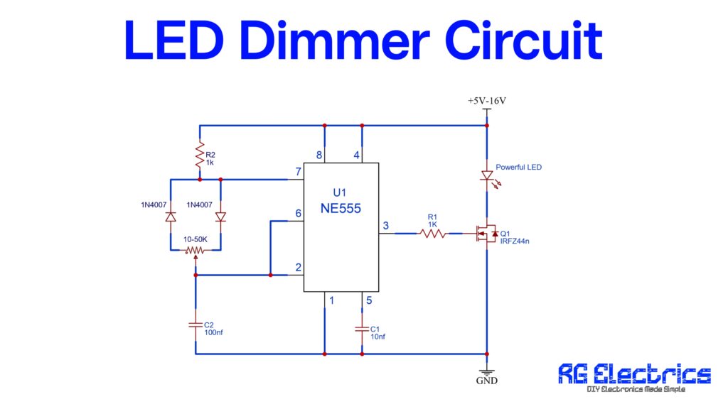
This LED Dimmer Circuit using NE555 timer IC is designed to control the brightness of a high-power LED by generating a variable PWM (Pulse Width Modulation) signal. The NE555 IC is configured in astable multivibrator mode, meaning it continuously produces pulses at its output (pin 3). The duty cycle of these pulses determines how long the LED remains ON during each cycle — thus controlling brightness.
A potentiometer (10–50KΩ) is connected along with two 1N4007 diodes, which direct the charging and discharging paths of capacitor C2 (100nF). This configuration allows independent adjustment of ON and OFF times of the PWM waveform. Resistors R1 and R2 help stabilize the timing network. The IRFZ44N MOSFET acts as a power driver that switches the LED according to the PWM signal from pin 3.
By turning the potentiometer knob, the pulse width increases or decreases, smoothly dimming or brightening the LED. The circuit operates efficiently from 5V to 16V DC, suitable for LED strips, bulbs, and automotive lighting applications. It provides precise control with minimal power loss, making it an ideal DIY dimmer project for beginners and hobbyists.
Applications
Here are some applications of the LED Dimmer Circuit using NE555:
- LED Brightness Control – Used to adjust the brightness of single LEDs or LED arrays smoothly without flickering.
- Automotive Lighting – Ideal for controlling the brightness of car interior or dashboard lights.
- DIY Lighting Projects – Commonly used in custom LED lamps, desk lights, and decorative lighting systems.
- Battery-Powered Devices – Helps extend battery life by reducing LED brightness when full intensity is not required.