Table of Contents
Introduction
A continuity tester is a handy electronic tool used to detect a complete path (continuity) in an electrical circuit. This device helps technicians, engineers, and DIY enthusiasts identify broken wires, PCB trace faults, or unconnected terminals. The circuit presented here is a simple yet effective continuity tester that uses a transistor, LED, and buzzer to indicate continuity. When a complete path is detected, the LED glows and the buzzer sounds, giving both visual and audible feedback. Powered by a small 5V battery, this tester is ideal for low-voltage applications and is extremely useful in electronics repair and prototyping work.
Components Details
| S.No | Component Name | Value | Quantity |
|---|---|---|---|
| 1 | Resistor | 4.7kΩ (R1) | 1 |
| 2 | Resistor | 100Ω (R2) | 1 |
| 3 | Transistor | BC547 or SL100 | 1 |
| 4 | LED | Red/Green | 1 |
| 5 | Buzzer | 5V DC Buzzer | 1 |
| 6 | Switch | SPST | 1 |
| 7 | Battery | 5V DC Supply | 1 |
| 8 | Connecting Wires | – | As needed |
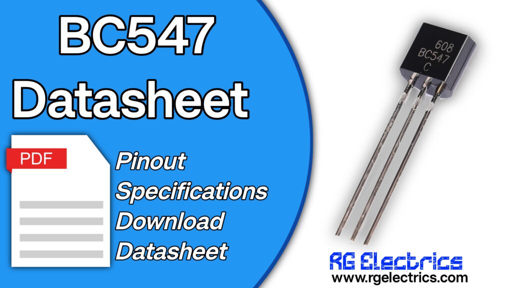
BC547 Pinout

Circuit Diagram

Circuit Explain
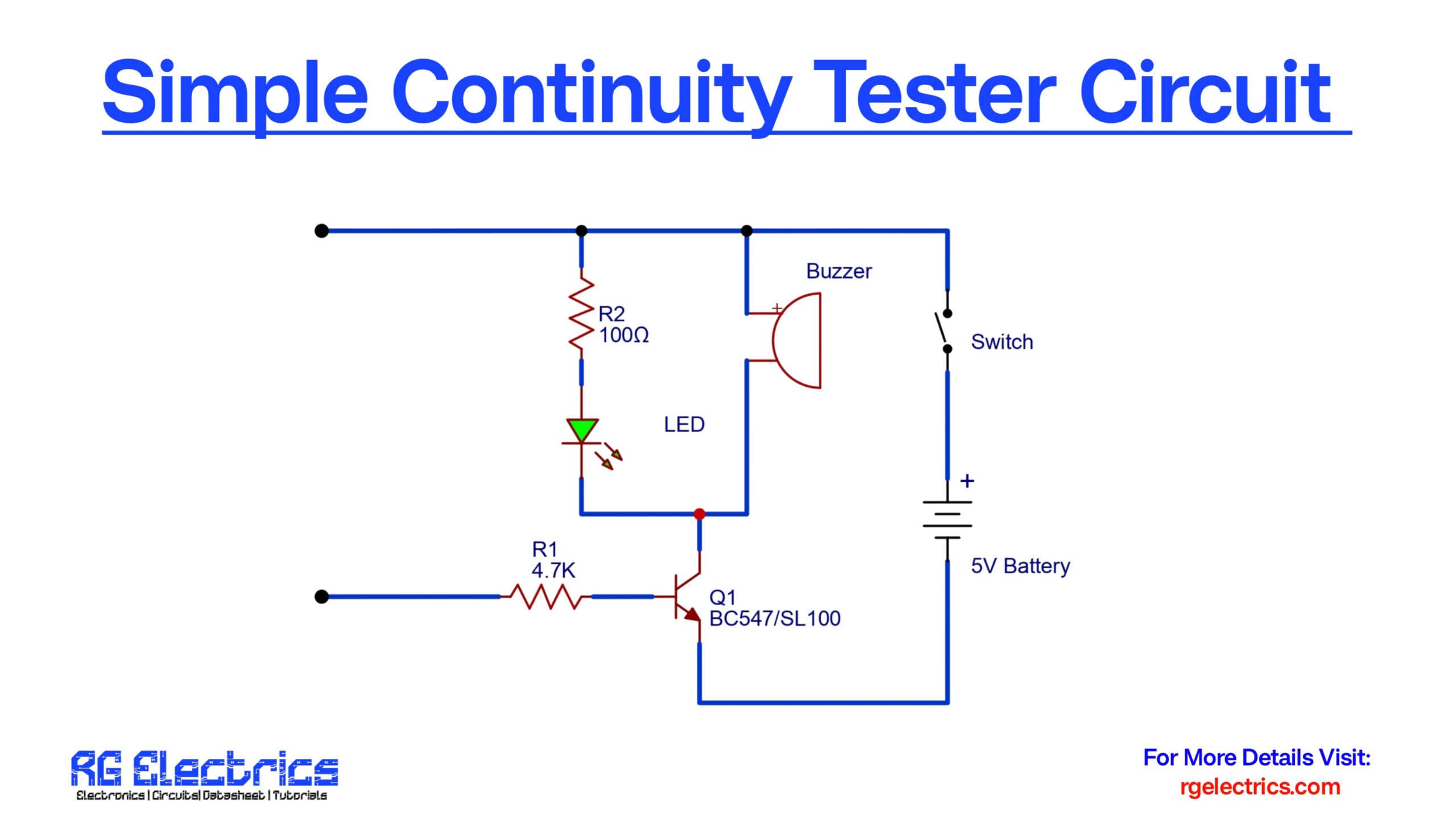
The circuit is centered around the NPN transistor (Q1 – BC547 or SL100) which acts as a switch. Here’s how it works:
- The base of the transistor is connected through a 4.7kΩ resistor (R1) to the test probes. When there is a closed path or continuity between the test probes, a small base current flows into the transistor.
- This base current turns ON the transistor, allowing current to flow from the collector to the emitter.
- As a result, the LED glows (indicating visual continuity) and the buzzer sounds (giving an audible alert), both connected in parallel.
- If there is no continuity, no base current flows, and the transistor remains OFF. Thus, the LED and buzzer remain inactive.
- The 100Ω resistor (R2) is used in series with the LED to limit current and protect it from burning out.
- A switch is included to turn the entire circuit on or off, conserving battery power when the tester is not in use.
This circuit is highly efficient because it uses very little power and is easy to build using common components.
Applications
- Testing electrical wiring and cables.
- Detecting PCB trace breaks.
- Verifying connectivity in breadboard circuits.
- Checking fuses or switches for continuity.
- Educational projects for electronics students.

