Table of Contents
Introduction
A seven-segment display is one of the most commonly used electronic display devices for representing numbers and certain characters in digital form. It consists of seven individual light-emitting diodes (LEDs) arranged in a specific pattern that can be illuminated in different combinations to form digits from 0 to 9. These displays are widely used in calculators, digital clocks, electronic meters, counters, and various measuring instruments where numerical output is required. The simple design, easy readability, and low power consumption make them a popular choice in electronics projects and consumer devices. Seven-segment displays come in two main types: common cathode and common anode, depending on how the LEDs are internally connected. They can be driven directly or through integrated circuits, such as decoders and counters. Due to their robustness and cost-effectiveness, seven-segment displays remain an essential component in both educational experiments and practical electronic applications.
Components Need
| Component | Value/Type | Quantity | Description/Use |
|---|---|---|---|
| Battery | 9V | 1 | Power supply for the circuit |
| IC1 | NE555 Timer IC | 1 | Generates clock pulses |
| IC2 | Decade Counter / Driver | 1 | Drives seven segment display (likely CD4026 or similar) |
| Seven Segment Display | Common Cathode Type | 1 | Displays digits 0–9 |
| R2 | 10kΩ Resistor | 1 | Timing resistor for 555 |
| R4 | 10kΩ Resistor | 1 | Timing resistor for 555 |
| R5 | 68kΩ Resistor | 1 | Timing control with capacitor |
| R6 | 10kΩ Resistor | 1 | Control for reset/clock enable |
| C1 | 1µF Capacitor | 1 | Timing capacitor for 555 |
| C2 | 22µF Capacitor | 1 | Stabilization/Timing capacitor |
| Switch (Count) | Push Button | 1 | Manual count input |
| Switch (Reset) | Push Button | 1 | Reset counter to zero |
| Connecting Wires | – | As required | For circuit connections |
| Breadboard/PCB | – | 1 | To assemble the circuit |
CD4026 Pinout

| Pin No. | Pin Name | Function |
|---|---|---|
| 1 | CLOCK | Receives clock input pulses to increment the counter. |
| 2 | CLOCK INHIBIT | When HIGH, clock pulses are inhibited (disabled). |
| 3 | DISPLAY ENABLE IN | Enables or disables the display (active HIGH). |
| 4 | DISPLAY ENABLE OUT | Used to cascade multiple CD4026 ICs. |
| 5 | CARRY OUT | Output carry for cascading counters. |
| 6 | f | Segment ‘f’ output of seven-segment display. |
| 7 | g | Segment ‘g’ output of seven-segment display. |
| 8 | VSS (GND) | Ground (0V). |
| 9 | d | Segment ‘d’ output of seven-segment display. |
| 10 | a | Segment ‘a’ output of seven-segment display. |
| 11 | e | Segment ‘e’ output of seven-segment display. |
| 12 | b | Segment ‘b’ output of seven-segment display. |
| 13 | c | Segment ‘c’ output of seven-segment display. |
| 14 | Ungated ‘C’ Segment | Provides an additional output for segment ‘c’. |
| 15 | RESET | Resets counter to zero (active HIGH). |
| 16 | VDD | Positive supply voltage (+3V to +15V, typically 5V or 9V). |
NE555 Pinout

| Pin No. | Name | Function/Description |
|---|---|---|
| 1 | GND | Ground – connected to the negative supply (0V). |
| 2 | TRIG | Trigger – starts the timing interval when voltage drops below 1/3 of Vcc. |
| 3 | OUT | Output – provides the output signal (high or low). |
| 4 | RESET | Reset – active low, resets the timing cycle when connected to ground. |
| 5 | CTRL | Control Voltage – adjusts threshold level, usually connected to a capacitor (0.01µF) to ground. |
| 6 | THRES | Threshold – compares voltage to 2/3 of Vcc, ends timing cycle when exceeded. |
| 7 | DISCH | Discharge – discharges the timing capacitor to ground. |
| 8 | VCC | Supply Voltage – connected to positive supply (typically +5V to +15V). |
Circuit Diagram

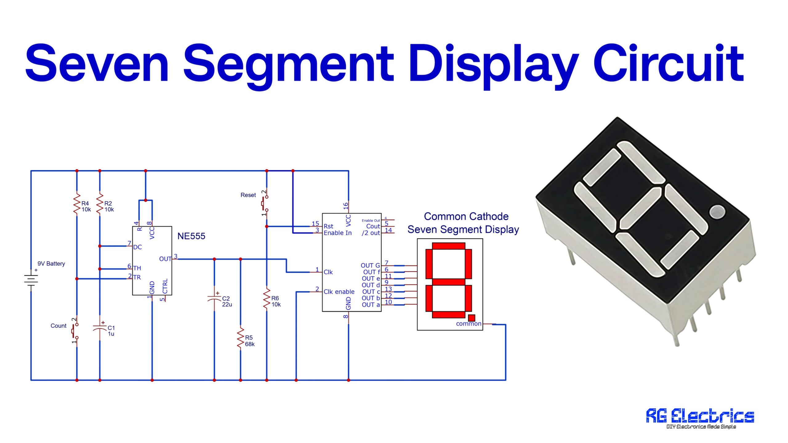
The circuit mainly has three important parts: Power Supply, Clock Generator (NE555), Counter IC, and Seven Segment Display.
- Power Supply
- A 9V battery is used to power the whole circuit.
- Proper connections ensure that both the NE555 timer IC and the counter IC get regulated voltage.
- Clock Pulse Generator (NE555 Timer)
- The NE555 timer IC is configured in astable mode.
- Resistors R2, R4, R5, R6 and capacitors C1, C2 decide the frequency of oscillation.
- The output of NE555 (pin 3) generates continuous square wave pulses, which act as the clock signal for the counter IC.
- These pulses are the “counting steps” that tell the counter when to increase the displayed number.
- Counter Section
- The clock pulses from NE555 go into a decade counter IC (often CD4017 or similar).
- This IC counts pulses sequentially and converts them into BCD (Binary Coded Decimal) outputs.
- The reset pin of the counter is connected with a reset switch, allowing the user to restart counting from zero.
- Seven Segment Display (Common Cathode)
- The counter’s outputs are connected to the seven-segment display.
- The display has 7 LEDs (a–g segments) arranged to form the digit “8.”
- According to the counter’s BCD output, different combinations of LEDs glow, forming digits from 0 to 9.
- Since it is a common cathode type, the common pin is grounded, and segments light up when they receive logic HIGH signals.
- Operation
- When the circuit is powered ON, the NE555 generates pulses.
- These pulses are counted by the counter IC and shown on the seven-segment display.
- Each new pulse increases the count, displaying the next number.
- The reset button allows restarting the counting process.
✅ In short: NE555 generates pulses → Counter counts pulses → Seven segment shows digits 0–9.
Applications of Seven Segment Display Circuit
- Digital Clocks
- Electronic Counters
- Calculators
- Scoreboards
- Measurement Instruments
- Timers
- Fuel Pumps
- Simple Digital Meters

