

Table of Contents
Introduction
Servo motors are widely used in robotics, automation, and industrial control systems due to their ability to provide precise angular positioning. To control a servo motor efficiently, a pulse width modulation (PWM) signal is required. The NE555 timer IC is a versatile component that can generate the necessary PWM signal to drive a servo motor. This article explores how to build a servo motor controller circuit using the NE555 timer, along with its working principles, components, and applications.
Components Required
To construct this circuit, you will need the following components:
- NE555 Timer IC – Generates the PWM signal
- Resistors: 10KΩ, 56KΩ, 220KΩ
- Capacitor: 10nF
- Diode: 1N4007 – Ensures proper current flow
- Power Supply: 5V DC
- Servo Motor
- Push Buttons (Forward & Reverse Switches)
NE555 Pinout

Circuit Diagram
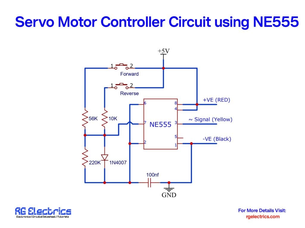
The circuit consists of an NE555 timer IC configured to generate a PWM signal. The forward and reverse switches help in adjusting the direction of rotation. The output from pin 3 of the NE555 timer is fed as a signal to the servo motor.
Working Principle
- PWM Signal Generation:
- The NE555 timer is configured as an astable multivibrator to produce a continuous PWM signal.
- The pulse width of the output signal determines the position of the servo motor.
- Direction Control:
- The circuit includes two switches labeled “Forward” and “Reverse.”
- Pressing the “Forward” switch increases the duty cycle, moving the servo motor in one direction.
- Pressing the “Reverse” switch decreases the duty cycle, moving the servo motor in the opposite direction.
- Role of Components:
- Resistors and Capacitors: These components determine the frequency and pulse width of the PWM signal.
- Diode (1N4007): Protects against reverse current and stabilizes the circuit.
- Power Supply (5V DC): Provides the necessary voltage to drive the servo motor and NE555 IC.
Applications
This servo motor controller circuit can be used in various applications, including:
- Robotics: Controlling robotic arm movements with precision.
- Industrial Automation: Used in conveyor belts and automated systems.
- RC Vehicles: Steering and throttle control in remote-controlled cars and airplanes.
- DIY Projects: Hobbyists can use it to experiment with servo motor control.
Advantages of Using NE555 for Servo Control
- Simple and Cost-effective: Requires minimal components and is easy to build.
- Reliable: NE555 timer is widely available and stable in operation.
- Customizable: Frequency and duty cycle can be adjusted by changing resistor and capacitor values.
Conclusion
The NE555 timer-based servo motor controller is an efficient and affordable way to control servo motors for various applications. By adjusting the PWM signal through the forward and reverse switches, precise control over the servo motor’s movement is achieved. Whether you’re a hobbyist or an engineer, this circuit provides a fundamental understanding of servo control using basic electronic components. Experiment with different resistor values to fine-tune the PWM signal according to your specific requirements.


