Skip to content
Menu
Home
Tools
Resistor Color Code Calculator
Capacitor Code to Value Calculator
Electronics Projects
Audio Amplifier Circuits
LED Light projects
BC547 Project
Transistor
NE555
Power Supply Circuits
Datasheets
Audio Amplifier Circuits
Contact Us
Menu
Home
Tools
Resistor Color Code Calculator
Capacitor Code to Value Calculator
Electronics Projects
Audio Amplifier Circuits
LED Light projects
BC547 Project
Transistor
NE555
Power Supply Circuits
Datasheets
Audio Amplifier Circuits
Contact Us
3.7v Smart Battery Charger Circuit
admin
December 19, 2024
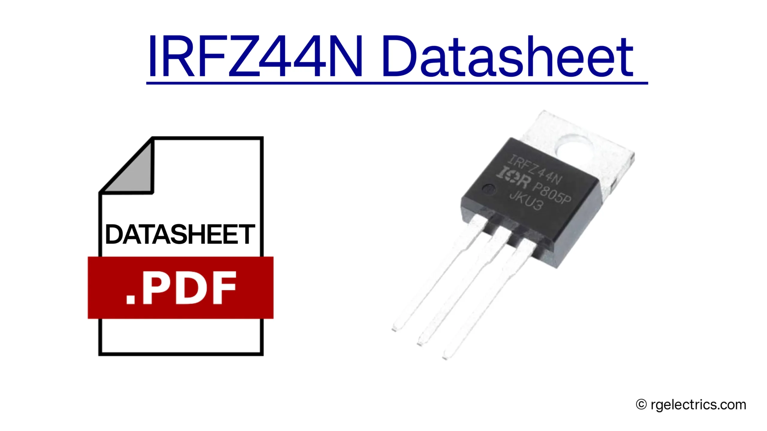
IRFZ44n Mosfet Datasheet, Pinout, Features & Applications
admin
December 17, 2024
Simple LED Dimmer Circuit Using IRFZ44n Mosfet
admin
December 16, 2024
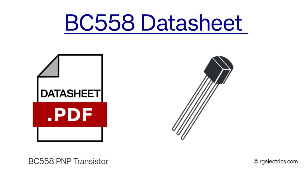
BC558 General-Purpose PNP Transistor Datasheet
admin
April 1, 2025
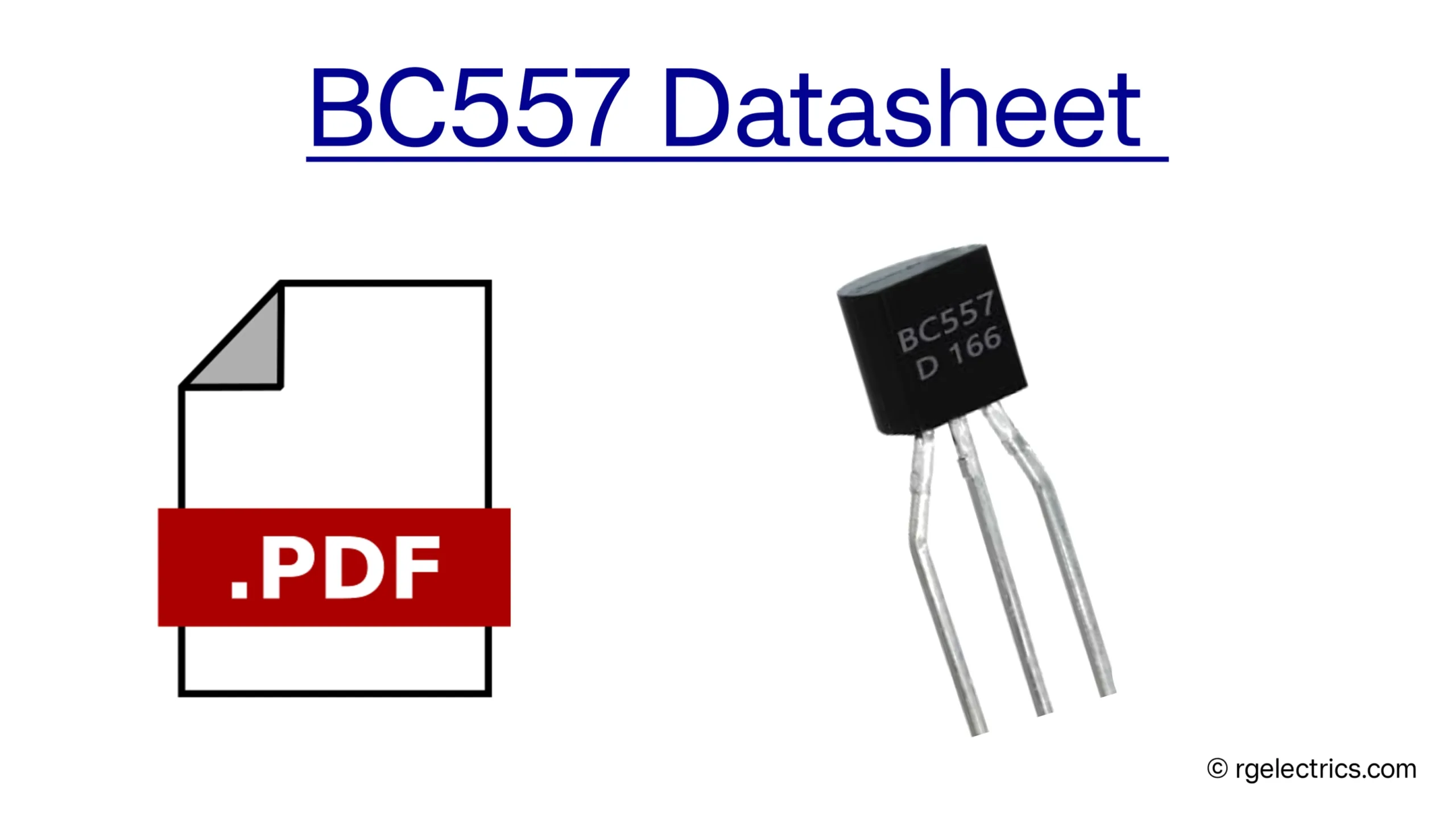
BC557 PNP Transistor Datasheet
admin
December 16, 2024
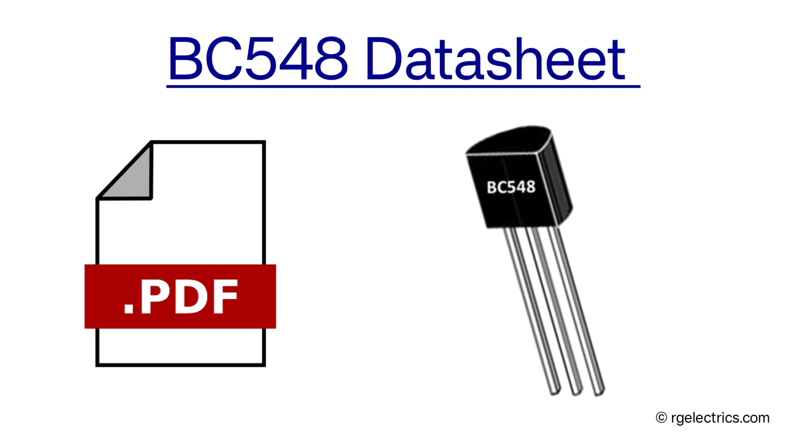
BC548 NPN Transistor Datasheet, Pinout, details
admin
December 16, 2024
BC547 NPN bipolar junction transistor (BJT) Datasheet
admin
December 16, 2024
5V to 12V Boost Converter Circuit
admin
December 14, 2024
12V To 24V DC-DC Boost Converter Circuit
admin
November 23, 2024
TDA2002 15W Bridge Audio Amplifier Circuit
admin
November 22, 2024
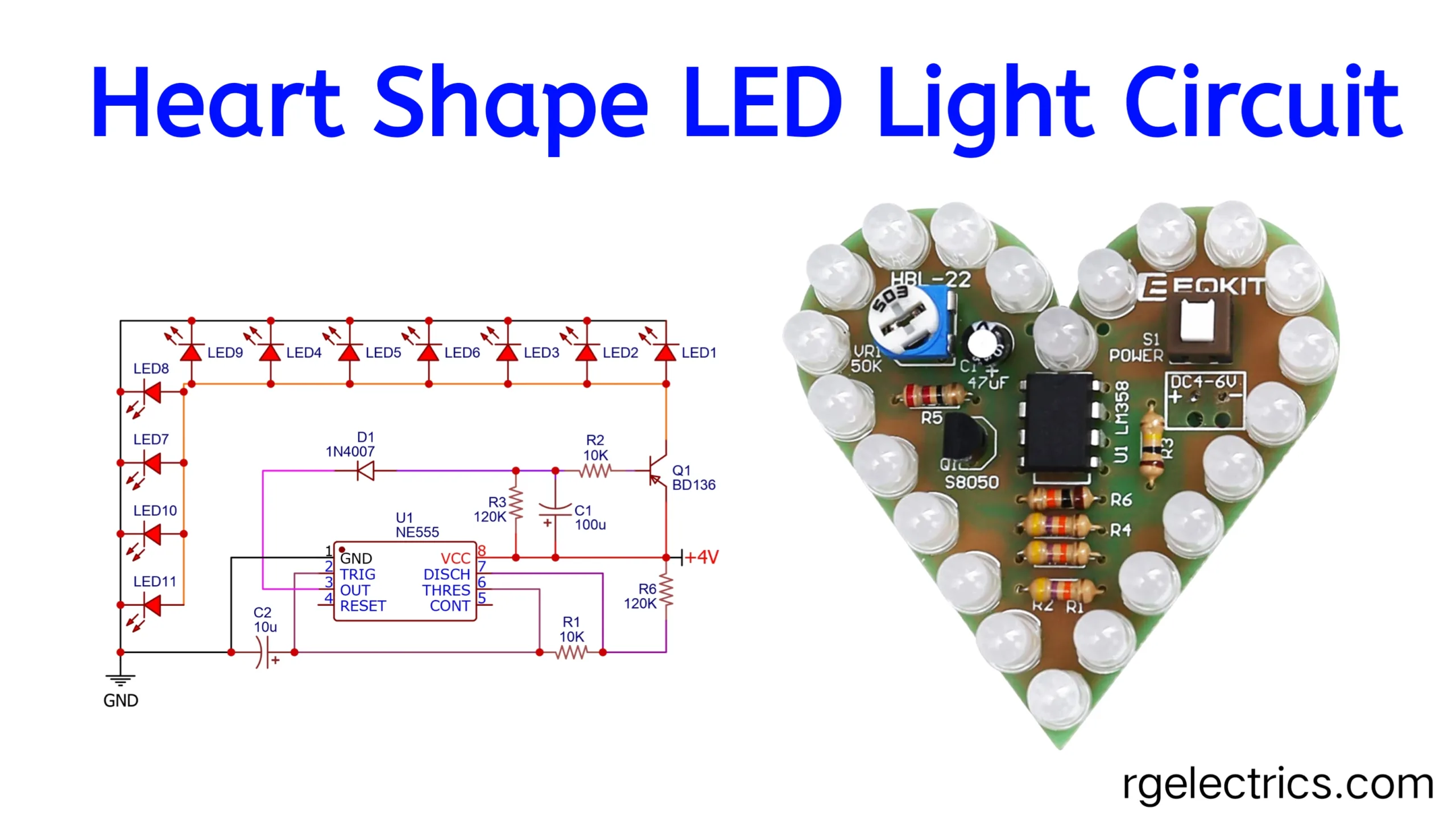
Heart Beating Effect LED Light Circuit NE555
admin
December 13, 2024
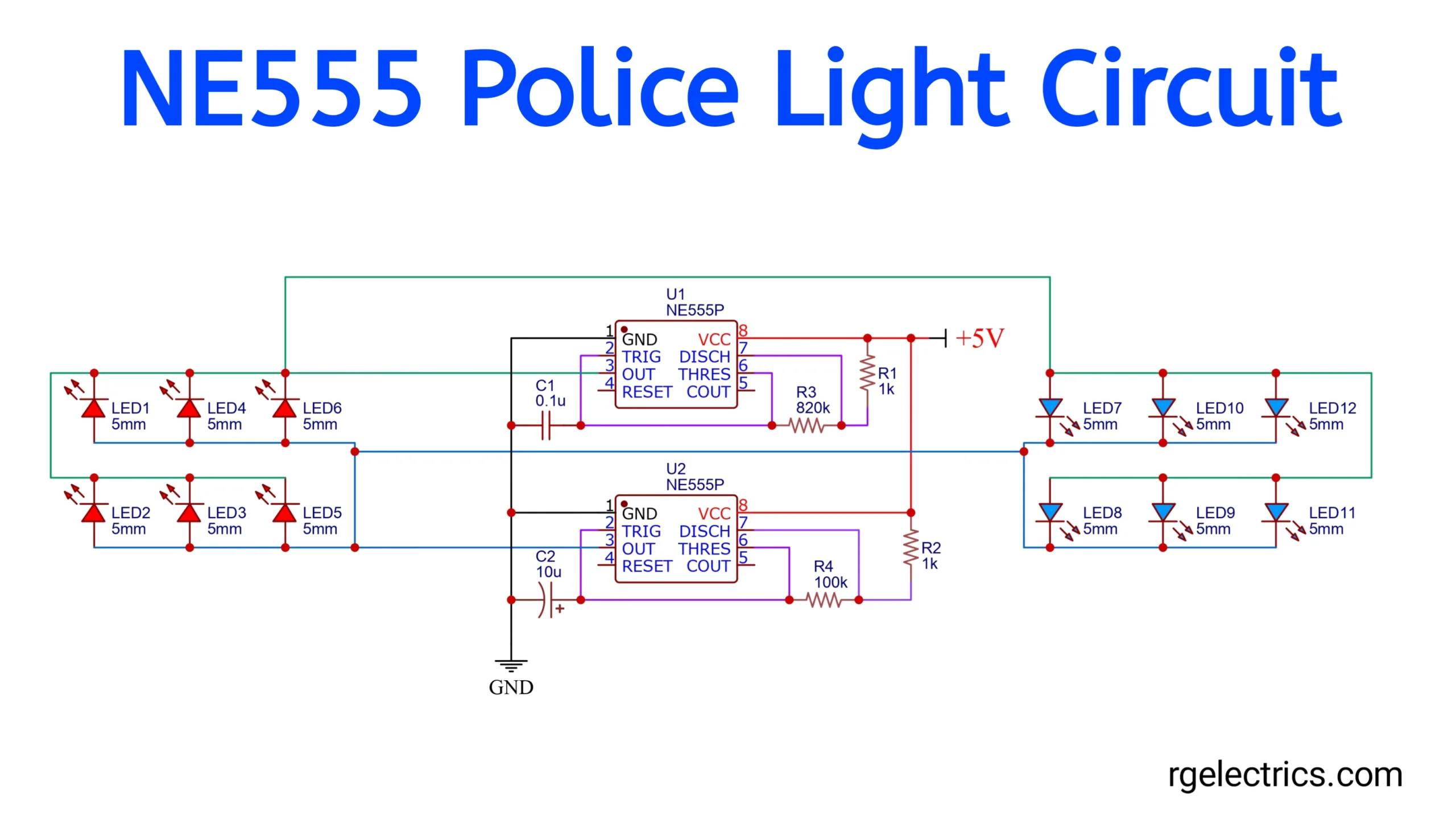
Simple Police LED Light Circuit using NE555
admin
November 22, 2024
TDA7052 1W Mono Audio Amplifier Circuit
admin
March 8, 2025
Auto Cut off 12V Battery Charger Circuit
admin
October 23, 2024
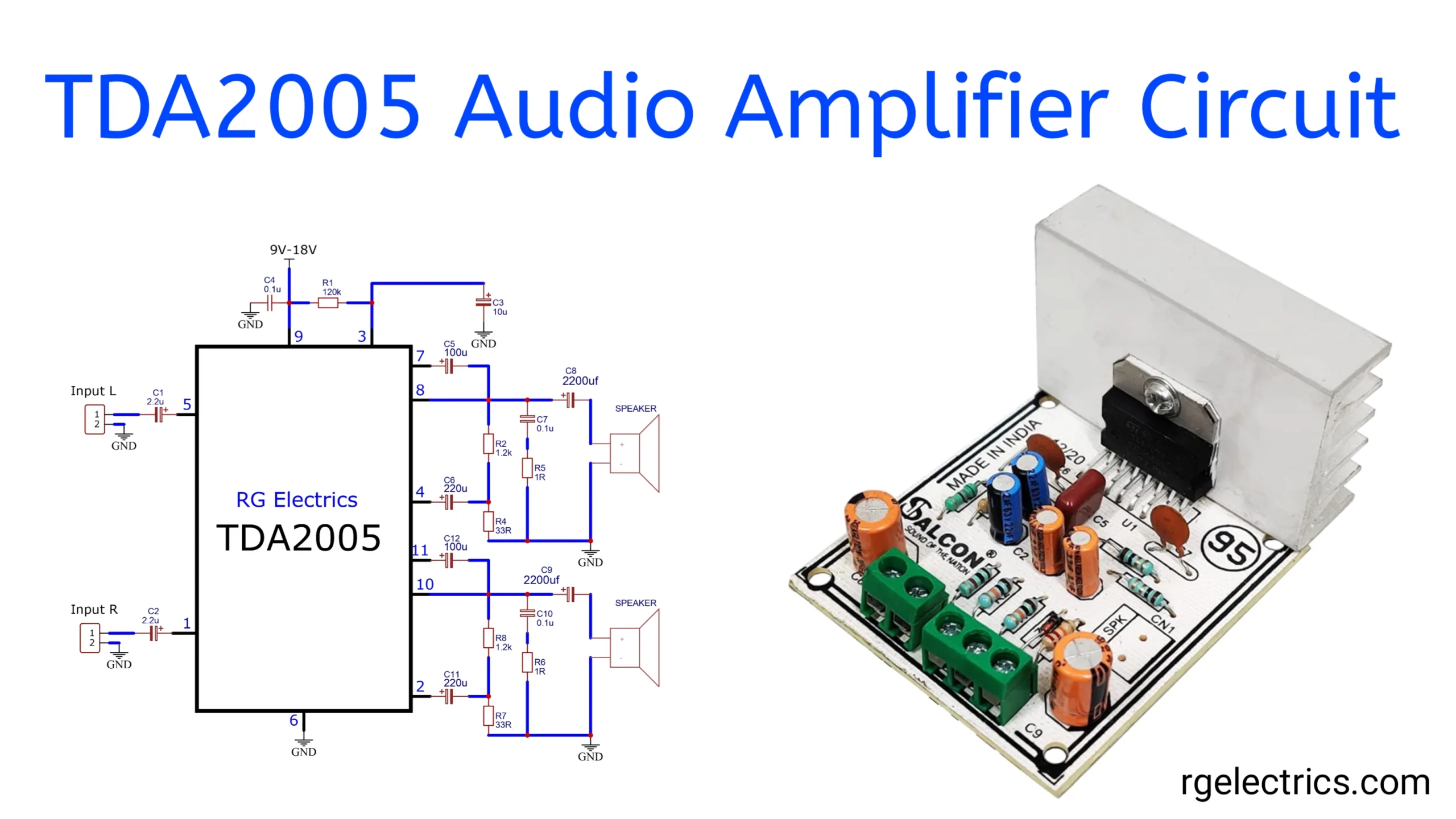
TDA2005 Stereo Audio Amplifier Circuit
admin
January 10, 2025
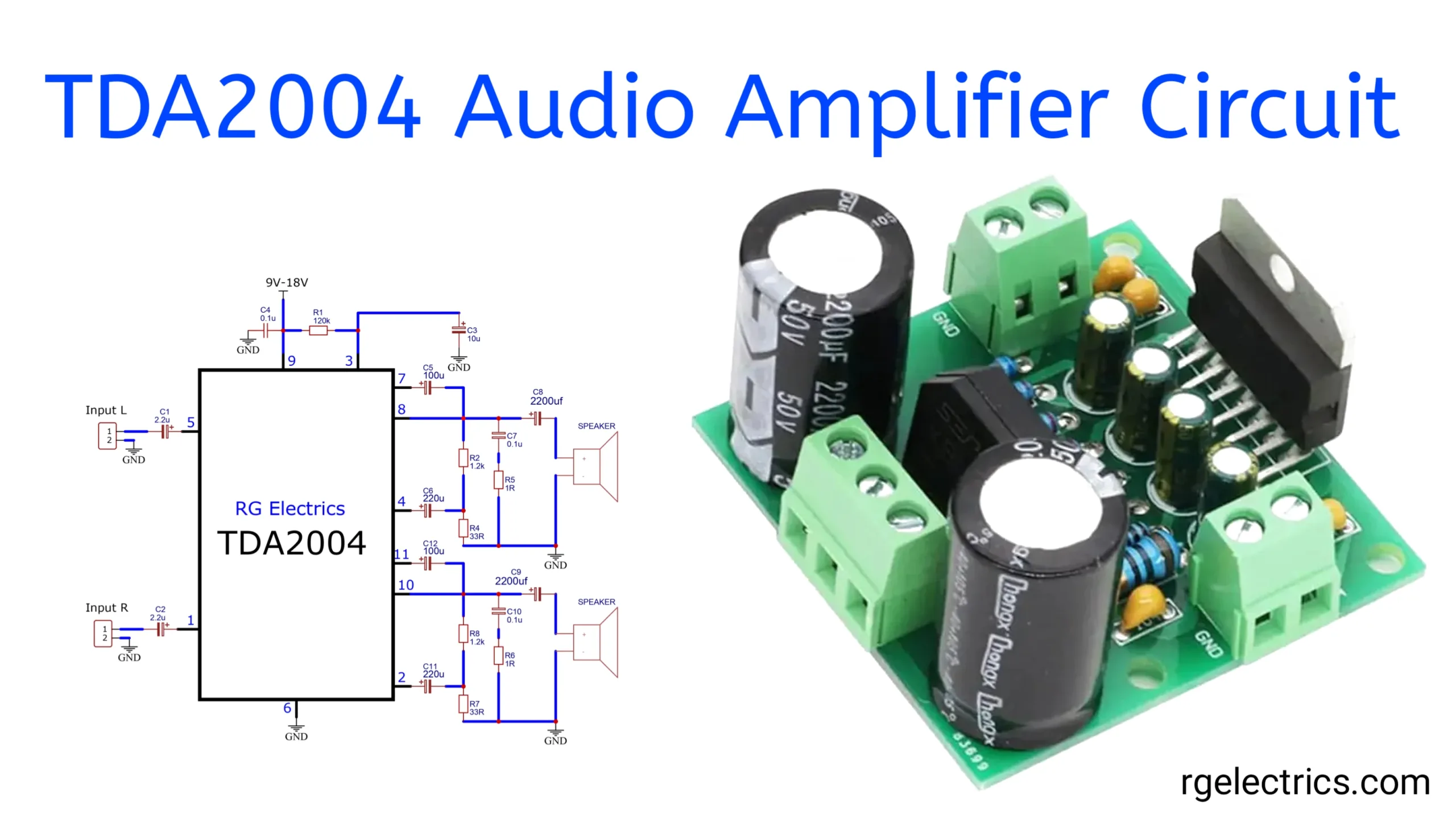
TDA2004 10W Stereo Audio Amplifier Circuit
admin
October 18, 2024
Previous
1
…
4
5
6
7
8
9
Next
Home
Tools
Resistor Color Code Calculator
Capacitor Code to Value Calculator
Electronics Projects
Audio Amplifier Circuits
LED Light projects
BC547 Project
Transistor
NE555
Power Supply Circuits
Datasheets
Audio Amplifier Circuits
Contact Us
Close
Search for: