

Table of Contents
Introduction
Servo motors are widely used in robotics, automation, and industrial control systems due to their ability to provide precise angular positioning. To control a servo motor efficiently, a pulse width modulation (PWM) signal is required. The NE555 timer IC is a versatile component that can generate the necessary PWM signal to drive a servo motor. This article explores how to build a servo motor controller circuit using the NE555 timer, along with its working principles, components, and applications.
Components Required
To construct this circuit, you will need the following components:
- NE555 Timer IC – Generates the PWM signal
- Resistors: 1KΩ, 2.2KΩ, 4.7KΩ, 33KΩ, 82KΩ
- Capacitor: 103 (10nF)
- Transistor: BC547 – Amplifies the output signal
- Power Supply: 5V DC
- Servo Motor
- Push Buttons (SB1 & SB2 for directional control)
NE555 Pinout

Circuit Diagram and Working Principle
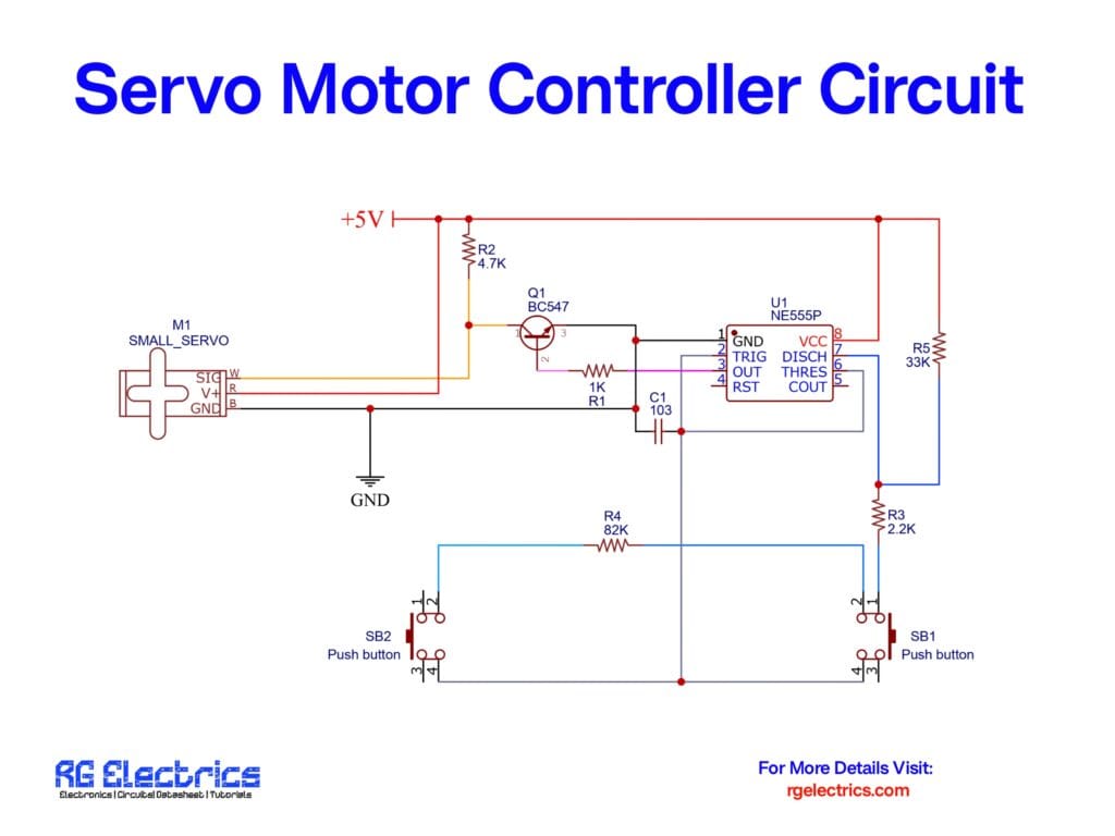
This servo motor controller circuit is designed using the NE555 timer in conjunction with a BC547 transistor for signal amplification. The working principle is as follows:
- PWM Signal Generation:
- The NE555 timer is configured to generate a continuous PWM signal.
- The pulse width of the output signal determines the position of the servo motor.
- Transistor (BC547) Role:
- The BC547 transistor acts as a switch to amplify the control signal.
- It ensures sufficient current is supplied to drive the servo motor properly.
- Direction Control with Push Buttons:
- The circuit includes two push buttons: SB1 and SB2.
- Pressing SB1 sends a signal to adjust the motor’s position in one direction.
- Pressing SB2 adjusts the motor’s position in the opposite direction.
- Role of Resistors and Capacitor:
- R1 (1KΩ): Limits base current for the transistor.
- R2 (4.7KΩ): Ensures stable operation of the transistor.
- R3 (2.2KΩ), R4 (82KΩ), and R5 (33KΩ): Help set the timing for PWM signal generation.
- C1 (103 or 10nF): Provides stability to the timer circuit.
Applications
This servo motor controller circuit can be used in various applications, including:
- Robotics: Controlling robotic arm movements with precision.
- Industrial Automation: Used in conveyor belts and automated systems.
- RC Vehicles: Steering and throttle control in remote-controlled cars and airplanes.
- DIY Projects: Hobbyists can use it to experiment with servo motor control.
- Smart Home Automation: Used in automated door openers, curtains, and security locks.
Advantages of Using NE555 for Servo Control
- Simple and Cost-effective: Requires minimal components and is easy to build.
- Reliable and Efficient: NE555 timer is widely available and stable in operation.
- Customizable: Frequency and duty cycle can be adjusted by changing resistor and capacitor values.
- Precise Control: Provides accurate positioning of servo motors for various applications.
Conclusion
The NE555 timer-based servo motor controller circuit, coupled with a BC547 transistor, offers an efficient and reliable method to control servo motors in various applications. By adjusting the PWM signal through the push buttons, precise control over the servo motor’s movement is achieved. This circuit is ideal for students, hobbyists, and engineers looking to understand servo motor control with basic electronic components. Experimenting with different resistor and capacitor values allows fine-tuning of the PWM signal to meet specific requirements.


