
Table of Contents
Introduction
Magnetic fields are invisible yet powerful forces that play a vital role in various scientific and industrial applications. Detecting them accurately is essential in everything from automation systems and consumer electronics to security devices and robotics. One of the most practical and cost-effective ways to detect a magnetic field is by using a Hall Effect sensor.
This article presents a simple yet effective Magnetic Field Detector Circuit designed using commonly available components such as the US1881 Hall Effect sensor, transistors, an LED, and a buzzer. The circuit is capable of detecting the presence of a magnetic field (specifically the south pole) and indicating its detection via visual and audible signals.
Whether you’re a hobbyist looking to explore basic electronics or a student working on a science project, this circuit offers an excellent opportunity to understand how magnetic sensors and transistor-based switching work together in a practical real-world application.
In this guide, we’ll walk through the components used, the working principle of the circuit, and its potential applications, along with tips to help you build it successfully.
Components Used
| Component | Specification | Description |
|---|---|---|
| U1 | US1881 | Hall Effect sensor (digital output) |
| Q1 | 2N3904 | NPN Transistor |
| Q2 | 2N3906 | PNP Transistor |
| R1 | 470Ω | Current-limiting resistor for LED |
| R2 | 1kΩ | Base resistor for Q2 |
| R3 | 220Ω | Base resistor for Q1 |
| LED | Standard LED | Indicates detection |
| Buzzer | DC Buzzer | Audio alert |
| Power Supply | 5V – 12V DC | Suitable for US1881 sensor |
2N3904 Pinout

2N3906 Pinout

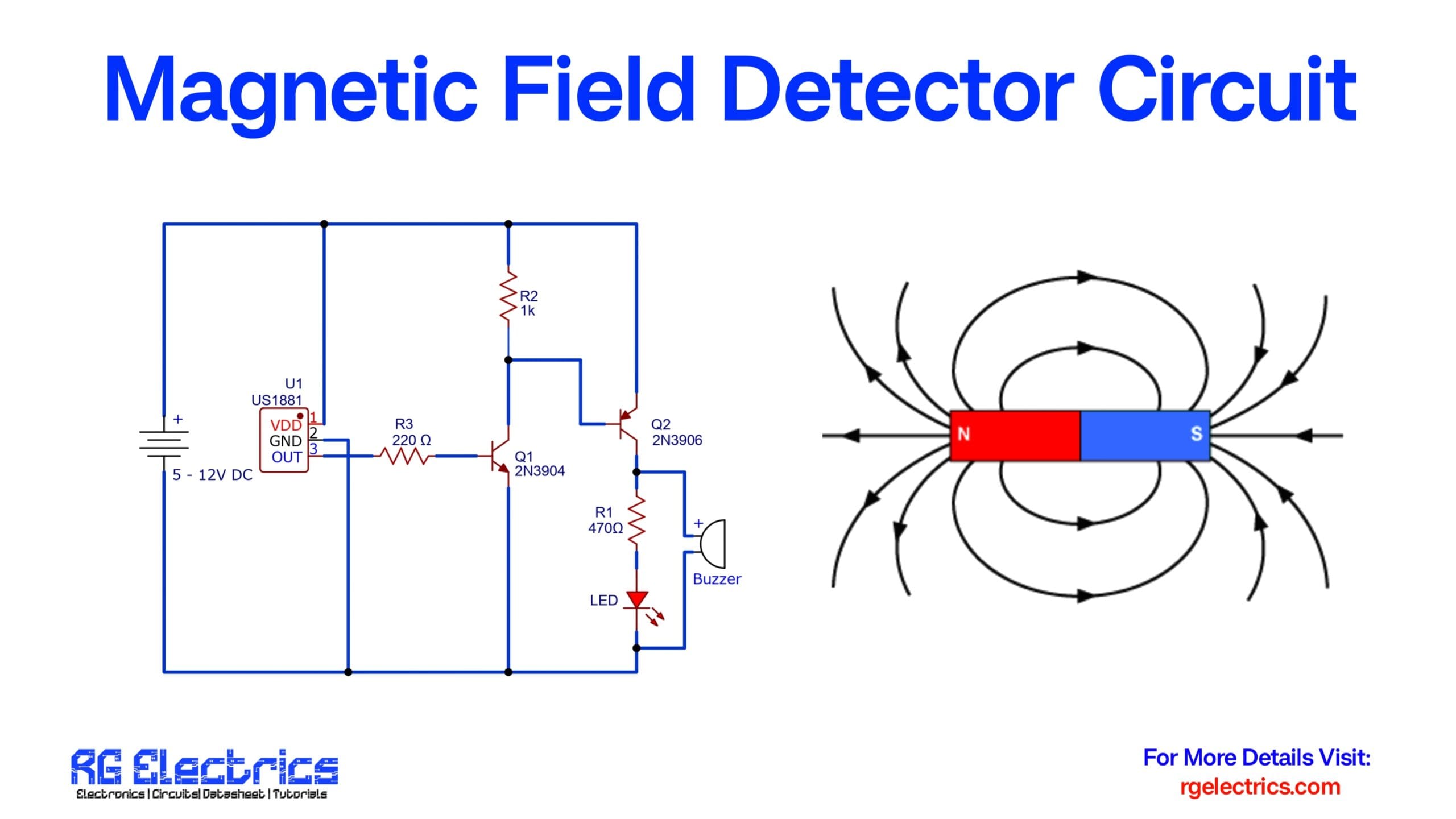
Circuit Diagram

How the Circuit Works
This circuit is designed around the US1881 Hall Effect sensor, which outputs a digital LOW signal when a magnetic field (south pole) is detected.
1. Power Supply
- A DC source of 5V to 12V powers the entire circuit.
- The US1881 Hall Sensor is powered via pin 1 (VDD) and grounded at pin 2 (GND).
2. Sensor Output
- When no magnetic field is present, the output (pin 3) of the Hall sensor remains HIGH.
- When a magnetic field is detected, the output goes LOW.
3. Transistor Switching Logic
- R3 (220Ω) feeds the output signal to the base of Q1 (2N3904), an NPN transistor.
- When the output is LOW (magnetic field detected), Q1 conducts and pulls the base of Q2 (2N3906) LOW via R2 (1kΩ).
- This turns ON Q2, allowing current to flow through the LED and Buzzer, activating both.
Visual Indicators
- LED Glows: Indicates a magnetic field has been detected.
- Buzzer Sounds: Provides an audible alert for magnetic detection.
Applications
- Proximity sensors
- Magnetic switches
- Security systems
- Industrial automation
- DIY electronics
Tips and Notes
- The circuit is highly sensitive to the south pole of a magnet.
- Ensure proper transistor orientation; otherwise, the circuit will not work.
- The US1881 is a unipolar Hall effect sensor—ideal for such detection circuits.
- You can omit the buzzer or LED based on your application needs.
Circuit Summary
- Input: Magnetic field (south pole)
- Output: Visual (LED) + Audible (Buzzer) signal
- Power: 5–12V DC
- Sensor: US1881 Hall Effect sensor
- Transistor Logic: NPN-PNP pair for switching


