Table of Contents
Introduction:
The LM3886 is a high-fidelity audio power amplifier IC from Texas Instruments, widely used in audio amplifier designs due to its excellent performance characteristics. It is capable of delivering up to 68 watts of continuous power to a 4Ω or 8Ω speaker with minimal distortion and noise. The IC features a built-in mute function, thermal protection, output short protection, and over-voltage protection, making it reliable and robust for audio applications.
In this specific circuit, the LM3886 is configured as a single-channel audio amplifier, designed to take an audio input, amplify it, and drive a speaker load with high efficiency. The circuit includes a feedback network, power supply filtering, compensation, and protection components to ensure stable, high-quality sound output.
This amplifier is ideal for use in home audio systems, subwoofers, or other high-power audio applications, where low distortion and high output power are essential. Its simplicity and ease of implementation make it a popular choice among hobbyists and professionals alike for building powerful and reliable audio systems.
Component Required:
| S.No | Components | Value | Qty. |
|---|---|---|---|
| 1. | Resistor | 10kΩ, 91kΩ, 75kΩ, 100kΩ, 1kΩ, 20kΩ, 10Ω, 2.7Ω | 1,1,1,1, 1,2,1,1 |
| 2. | Capacitor | 10µF, 0.1µF, 220pF, 4700µF/50V, 100µF, 50pF, 0.1µF | 1,2,1,1,1,1,1 |
| 3. | Inductor | 0.7µH | 1 |
| 4. | Transistor | 2N3904 | 1 |
| 5. | Potentiometer (Optional) | 10kΩ | 1 |
| 6. | LM3886 IC | Audio Amplifier IC | 1 |
| 7. | Speaker | 8Ω | 1 |
Pinout of LM3886 IC:
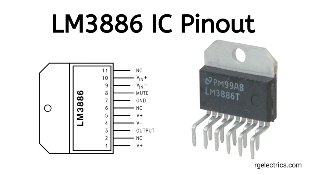
LM3886 Pin Descriptions:
- V+: Positive power supply (typically +28V to +42V).
- NC: No connection (not used).
- Output: Output to the speaker.
- V-: Negative power supply (typically -28V to -42V).
- V+: Positive power supply (second pin connected to the positive supply).
- NC: No connection (not used).
- Ground (GND): Ground connection for the IC.
- Mute: Mute function pin. It can be used to mute or unmute the amplifier.
- V_IN−: Inverting input of the amplifier.
- V_IN+: Non-inverting input of the amplifier.
- NC: No connection (not used).
Circuit Diagram:
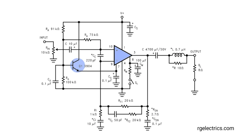
Circuit Explaination:
LM3886 IC, a high-performance audio amplifier IC capable of delivering up to 68W of output power with minimal distortion. Let walk through the key parts of this circuit:
1. Input Stage:
- The input signal enters through the 10kΩ resistor.
- There is a coupling capacitor(10µF), which blocks any DC component from the input signal, allowing only the AC (audio) signal to pass.
- The transistor Q1 (2N3904) is used to amplify or buffer the input signal before it is sent to the amplifier. It’s a common small signal NPN transistor.
2. LM3886 Operational Amplifier:
- The LM3886 chip itself is shown in the middle of the diagram.
- Pin 1 and Pin 10 are the inverting and non-inverting inputs, respectively.
- Pin 3 is the output, connected to the speaker load via an LC filter, which minimizes high-frequency oscillations and stabilizes the output.
3. Feedback Network:
- The resistors (20kΩ) and (20kΩ) form the feedback loop that controls the gain of the amplifier.
- A capacitor (50pF) is placed in parallel with ( RF 1) to stabilize the amplifier at high frequencies.
4. Bootstrap Capacitor and Zobel Network:
- The capacitor (220pF) between pins 1 and 10 serves as a compensation capacitor, controlling the frequency response of the amplifier.
- The Zobel network (R = 10Ω and C = 0.1µF) connected at the output ensures stability and reduces high-frequency noise in the amplifier output.
5. Power Supply:
- The circuit requires both positive and negative voltage rails ( ( V+ ) and ( V- ) ). The power supply decoupling capacitors ( CS ) (large electrolytic capacitors) stabilize the power supply and minimize any ripple that could enter the audio signal.
- The 4700µF capacitor near the output stage helps filter the power to provide clean DC voltage to the amplifier.
6. Output Stage:
- The output from pin 3 of the LM3886 is sent through an inductor (L = 0.7µH) and a resistor (R = 10Ω) before being fed to the load, which is an 8Ω speaker. The inductor helps in reducing high-frequency noise, while the resistor limits current spikes.
7. Capacitive and Resistive Compensation (Optional):
- The resistors ( R_SN) (2.7Ω) and capacitors ( C_SN ) (0.1µF) form an optional snubber network that helps in stabilizing the circuit in the case of oscillations or other instability.
Working:
- When an audio signal is applied to the input, it gets amplified through the transistor ( Q1 ) and then fed into the non-inverting input of the LM3886 amplifier.
- The gain of the amplifier is controlled by the feedback network.
- The amplified output is then filtered to remove any high-frequency noise and fed to the speaker load.
Applications:
- Home Audio Systems
- Subwoofer Amplifiers
- Public Address (PA) Systems
- Guitar Amplifiers
- Powered Speakers
- DIY Audio Projects
- Car Audio Systems


