Table of Contents
Modern home security systems are becoming smarter, simpler, and more user-friendly. One such innovative solution is the Electric Touch Door Lock Circuit, which unlocks your door with a simple touch using a TTP223 touch sensor, a relay module, and a 12V electric lock. This circuit is ideal for DIY home automation projects, cabinets, lockers, and low-cost smart door systems.
This article explains the complete working, wiring diagram, components used, advantages, and applications of this project in detail.
Introduction
The Electric Touch Door Lock System is a touch-based locking mechanism that activates an electric lock whenever you touch the TTP223 capacitive touch sensor. Unlike traditional password locks or key-based systems, this setup is simple, reliable, and easy to build.
The core idea is straightforward:
- The TTP223 touch sensor detects a touch.
- It triggers the relay module.
- The relay switches the 12V power to activate the electric lock.
- The lock pulls back its latch and the door opens.
This project uses two different batteries:
- A 12V battery pack (made with 18650 cells) to power the electric lock.
- A 3.7V Li-Ion battery to power the touch sensor and relay module.
The circuit is safe, energy-efficient, and ideal for beginners learning about touch-based automation.
Components Used in the Circuit
| Component | Description |
|---|---|
| TTP223 Touch Sensor Module | Capacitive sensor that outputs HIGH when touched |
| Relay Module (5V) | Controls switching of 12V electric lock |
| 12V Electric Lock | Door/cabinet latch that activates when powered |
| 12V Battery Pack (3 × 18650 cells) | Powers the electric lock |
| 3.7V Li-Ion Battery (Single 18650) | Powers the sensor and relay |
| Connecting Wires | For wiring the circuit |
| Mounting Accessories | Optional, for installation |
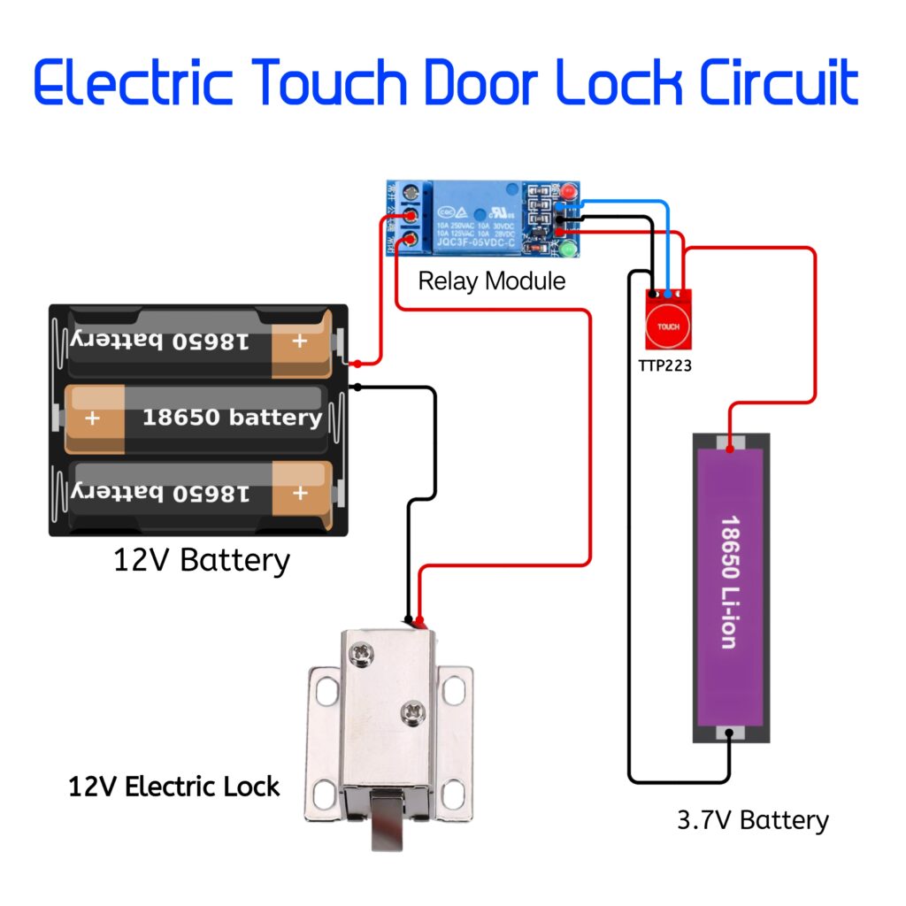
Circuit Diagram
Working of the Electric Touch Door Lock Circuit
1. Touch Activation (TTP223 Sensor)
The TTP223 capacitive touch module senses a finger touch and outputs a HIGH signal.
This HIGH output goes to the IN pin of the relay module, triggering it instantly.
2. Relay Switching
When the relay receives the HIGH signal:
- The relay coil energizes.
- The COM and NO terminals of the relay connect.
- This provides 12V power to the electric lock.
3. Electric Lock Activation
The 12V electric lock requires a high-current pulse to retract the metal latch.
When the relay switches:
- The lock receives power.
- Its latch pulls back.
- The door opens automatically.
Once the touch is released:
- The sensor output returns LOW.
- The relay turns OFF.
- The lock returns to its locked position.
4. Why Two Batteries?
| Load | Required Voltage | Supplied By |
|---|---|---|
| Sensor + Relay | 3.3V – 5V | 3.7V Li-ion battery |
| Electric Lock | 12V | 12V (3 × 18650) battery pack |
This separation ensures:
- Long battery life
- No voltage spikes on the sensor
- Stable operation of relay and lock
Circuit Explanation (Step-by-Step)
- 3.7V battery powers the TTP223 touch sensor and the relay module.
- The TTP223 output pin is connected to the IN terminal of the relay.
- When touched, the sensor sends a HIGH signal to activate the relay.
- The 12V battery pack is connected to the lock through the relay’s COM and NO terminals.
- When relay switches ON, it completes the 12V circuit and powers the electric lock.
- The lock opens; releasing touch closes the lock again.
Circuit Advantages
- No keys required – open the door with a simple touch
- Low cost & easy DIY project
- Low power consumption
- Works with any metallic or non-metallic touch surface
- Compact and reliable
- Ideal for cabinets, lockers, drawers, and secret compartments
Applications
- Home and room doors
- Office drawer locking system
- Smart locker systems
- Wardrobe and cabinet access
- Hidden/secret door locking
- Safety boxes and tool cabinets