Table of Contents
Introduction
The Clap Switch is a simple yet fascinating electronics project that demonstrates sound detection and automatic switching. This circuit uses a condenser microphone to detect sound (like a clap) and a NE555 Timer IC to process the signal and switch an output device — in this case, an LED.
This kind of project is commonly used in sound-activated lights, appliances, or security systems. With its minimal components and ease of understanding, it’s ideal for electronics hobbyists and beginners looking to explore the fundamentals of analog signal detection and timer-based switching.
Components Required
| S.No | Component Name | Value | Quantity |
|---|---|---|---|
| 1 | NE555 Timer IC | — | 1 |
| 2 | Condenser Mic | — | 1 |
| 3 | Transistor | BC547 | 1 |
| 4 | Resistor | 1kΩ | 1 |
| 5 | Resistor | 47kΩ | 1 |
| 6 | Resistor | 100kΩ | 1 |
| 7 | Resistor | 220Ω | 1 |
| 8 | Capacitor | 10µF | 1 |
| 9 | LED | Red | 1 |
| 10 | Battery | 9V | 1 |
| 11 | Breadboard/Wires | — | As needed |
NE555 Pin Configuration

| Pin No. | Function |
|---|---|
| 1 | GND |
| 2 | Trigger |
| 3 | Output |
| 4 | Reset |
| 5 | Control Voltage |
| 6 | Threshold |
| 7 | Discharge |
| 8 | Vcc (+9V) |
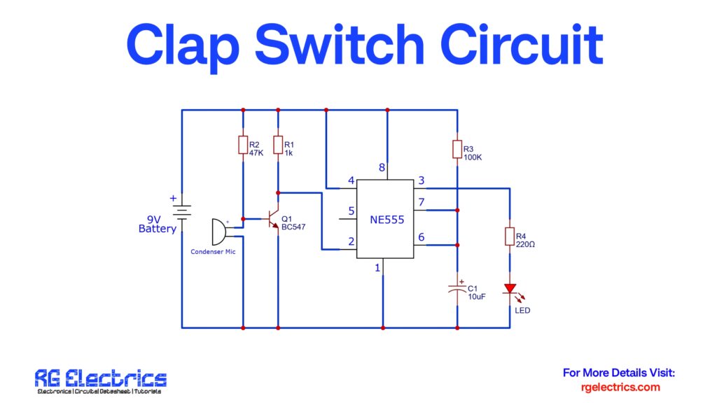
Circuit Diagram
Circuit Explanation
Working Principle:
The circuit operates by detecting a sharp sound pulse like a clap using a condenser microphone. The mic converts the sound into a small voltage signal. This signal is too weak to drive any load, so it is first amplified using a BC547 transistor. The amplified signal then triggers the NE555 timer IC, configured in monostable mode.
🔁 Step-by-Step Explanation:
- Sound Detection:
- The condenser microphone picks up sound vibrations and produces a small AC signal.
- This signal is sent to the base of the BC547 transistor via a 1kΩ resistor (R1).
- Signal Amplification:
- The BC547 transistor amplifies the signal and acts as a switch.
- When sound is detected, it sends a short high pulse to pin 2 (trigger) of the NE555 IC.
- 555 Timer Response:
- NE555 is configured in monostable mode. Upon receiving the trigger, it switches its output (pin 3) to HIGH for a short duration.
- This ON time is controlled by R3 (100kΩ) and C1 (10µF).
- LED Activation:
- The HIGH output from pin 3 is fed through a 220Ω resistor (R4) to an LED.
- The LED lights up briefly to indicate the detection of a clap.
- Resetting:
- After a short delay (defined by RC timing), the output goes LOW again, turning the LED off.
- The circuit resets and becomes ready to detect the next clap.
Applications
- Children’s toys with sound response
- Simple security or alert systems
- Learning project for NE555 timer circuits