

Table of Contents
Introduction
A servo motor is a crucial component in many electronic and robotic applications. It allows precise control of angular movement and is widely used in automation, robotics, and hobby projects. In this article, we will explore how to build a simple servo motor driver circuit using the NE555 timer IC.
Components Required
To construct this circuit, you will need the following components:
- NE555 Timer IC
- Resistors: 10KΩ, 50KΩ (Variable), 240KΩ
- Capacitors: 120nF, 10nF
- Diode: 1N4007
- 5V DC Power Supply
- Servo Motor
NE555 Pinout

Circuit Diagram
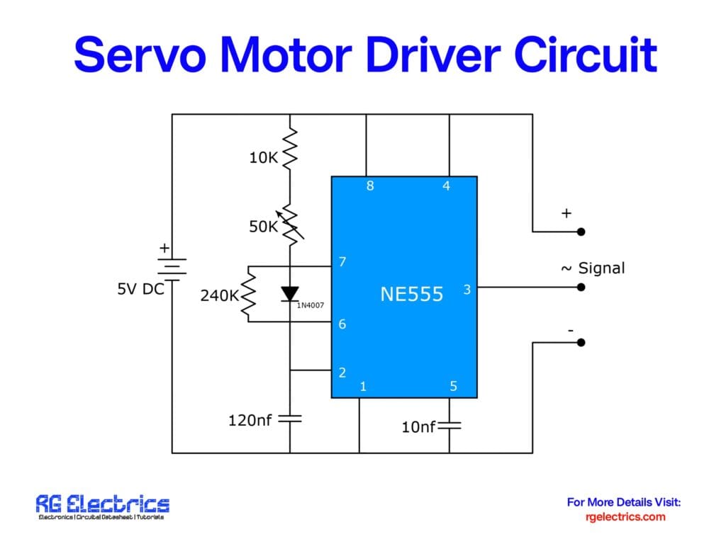
The circuit diagram consists of an NE555 timer IC in an astable multivibrator configuration. The output signal from pin 3 is used to drive the servo motor. The variable resistor (50KΩ) helps adjust the pulse width, which in turn controls the servo motor’s position.
Working Principle
- The NE555 timer generates a PWM (Pulse Width Modulation) signal at pin 3.
- The resistor and capacitor network sets the frequency and duty cycle of the signal.
- The diode (1N4007) ensures proper current flow and protects the circuit.
- The servo motor receives the PWM signal and adjusts its position accordingly.
Applications
This simple servo motor driver circuit is ideal for:
- Robotics
- Remote-controlled vehicles
- Automated systems
- Hobby electronics projects
Conclusion
By using an NE555 timer IC, you can create a cost-effective and efficient servo motor driver circuit. This circuit allows you to control a servo motor’s position with precision, making it a valuable tool for various applications. Experiment with different resistor values to fine-tune the PWM signal according to your needs.


