Table of Contents
Introduction
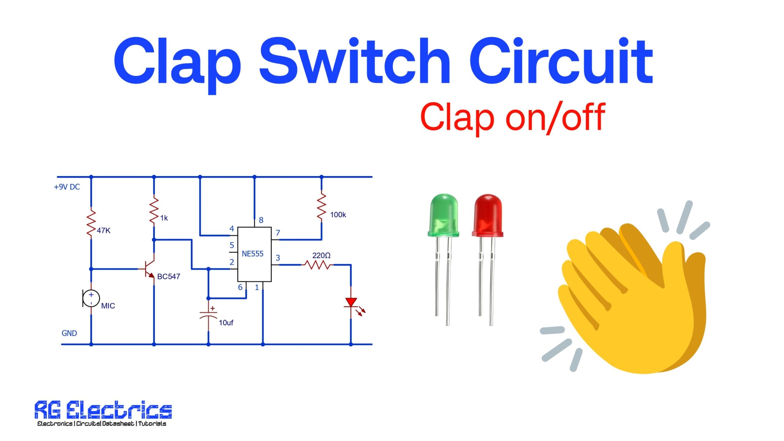
The clap switch circuit is a simple sound-activated switch that can be used to turn ON or OFF electrical appliances with a clap sound. It is widely used in home automation and electronic projects to control devices without physical contact. This circuit utilizes a NE555 timer IC, a microphone, and a transistor to detect sound and trigger the output.
Components Required
| Component | Specification |
|---|---|
| NE555 Timer IC | – |
| Electret Microphone | – |
| Resistor | 47KΩ, 1KΩ, 100KΩ, 220Ω |
| Capacitor | 10µF |
| Transistor | BC547 |
| LED | Indicator |
| Power Supply | 9V DC |
NE555 Pinout

Circuit Diagram
The following is the circuit diagram for the clap switch using NE555 timer:

Working Principle
The clap switch works based on sound detection and timing. Here’s how it functions:
- Sound Detection:
- The microphone detects the clap sound and generates a small electrical signal.
- This signal is amplified using the BC547 transistor.
- Pulse Generation:
- The amplified signal is fed to the NE555 timer at pin 2 (Trigger Pin).
- The NE555 timer operates in monostable mode, meaning it produces a single output pulse whenever triggered.
- Output Activation:
- The timer turns ON the LED (or relay to control an appliance) for a short duration.
- The output duration is controlled by the capacitor (10µF) and resistor (100KΩ) connected to the timer.
Applications
The clap switch circuit can be used in various applications, including:
- Home Automation: Turning ON/OFF lights or fans with a clap.
- Assistive Technology: Helping physically challenged individuals control devices easily.
- Security Systems: Integrating with alarm systems for sound-based activation.
- Toys and Gadgets: Creating interactive sound-responsive electronic projects.
Advantages
- No physical contact required for operation.
- Low-cost and easy-to-build circuit.
- Works with various appliances using a relay.
- Consumes minimal power due to the NE555 timer’s efficiency.
Conclusion
The Clap Switch Circuit using NE555 Timer is a practical and simple project that showcases how sound signals can be converted into electrical signals to control devices. With further modifications, this circuit can be improved to add more sensitivity or a toggle function for better usability in real-life applications.


