Table of Contents
Introduction
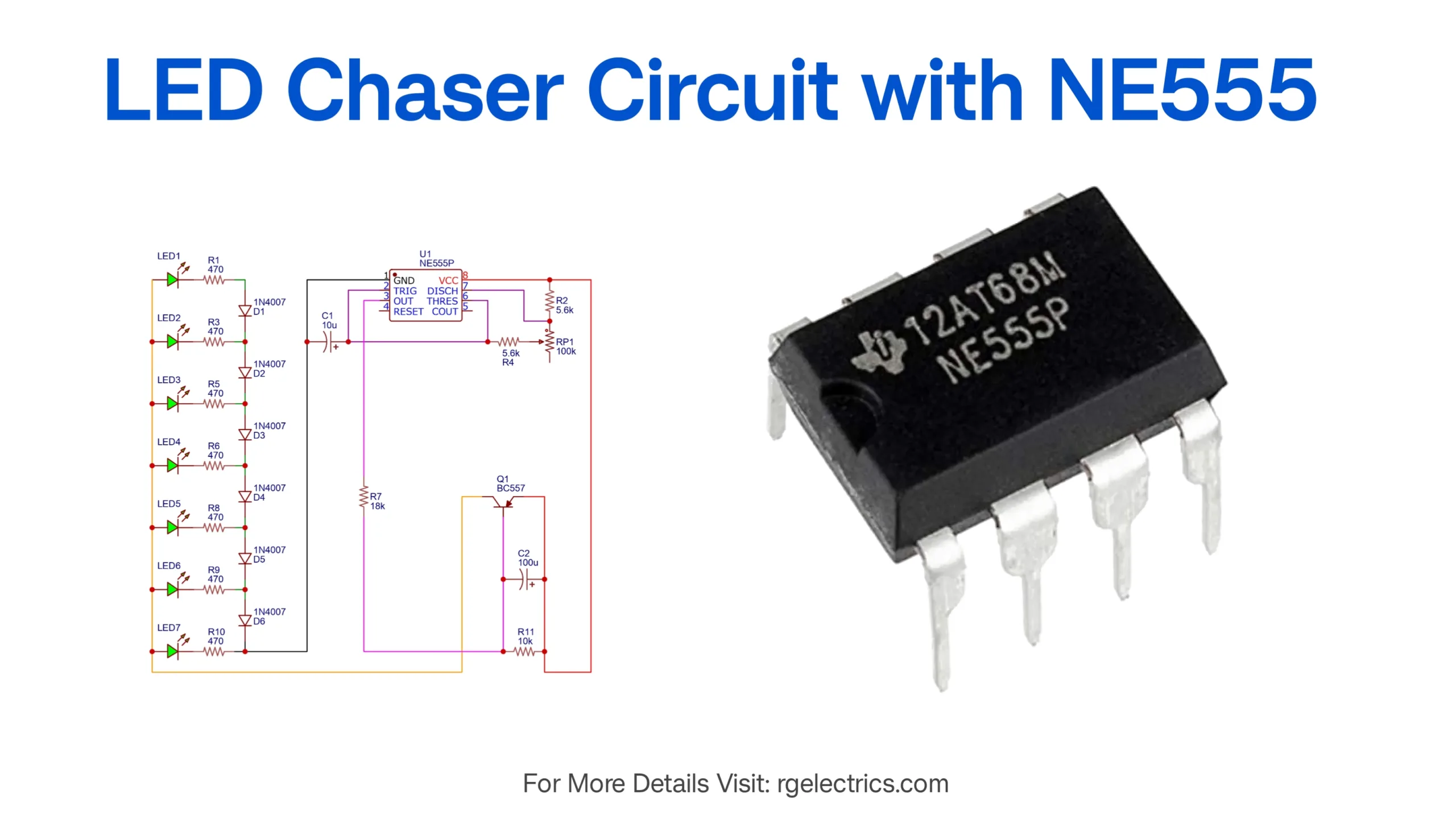
A LED Chaser Circuit is a simple yet engaging project that sequentially turns on and off LEDs in a predefined pattern, creating a chasing effect. This type of circuit is commonly used in decorative lighting, running lights, and display systems. The core of this circuit is the NE555 timer IC, which generates the required clock pulses to drive the LEDs sequentially. This project is ideal for beginners interested in electronics and timer-based circuits.

Components List
To build this LED chaser circuit, you will need the following components:
- ICs & Transistors:
- NE555 Timer IC – 1 piece
- BC557 PNP Transistor – 1 piece
- LEDs (Light Emitting Diodes):
- 7 pieces (any color, preferably red or green for better visibility)
- Resistors:
- 470Ω – 7 pieces (for limiting LED current)
- 5.6kΩ – 2 pieces
- 10kΩ – 1 piece
- 18kΩ – 1 piece
- Capacitors:
- 10µF – 1 piece (for timing stabilization)
- 100µF – 1 piece (for smooth power supply)
- Diodes:
- 1N4007 – 6 pieces (to ensure correct LED sequencing)
- Variable Resistor (Potentiometer):
- 100kΩ – 1 piece (to adjust LED chase speed)
- Power Supply:
- 5V-12V DC (depending on LED requirements)
- Connecting Wires & Breadboard or PCB for assembly
NE555 Timer Pinout
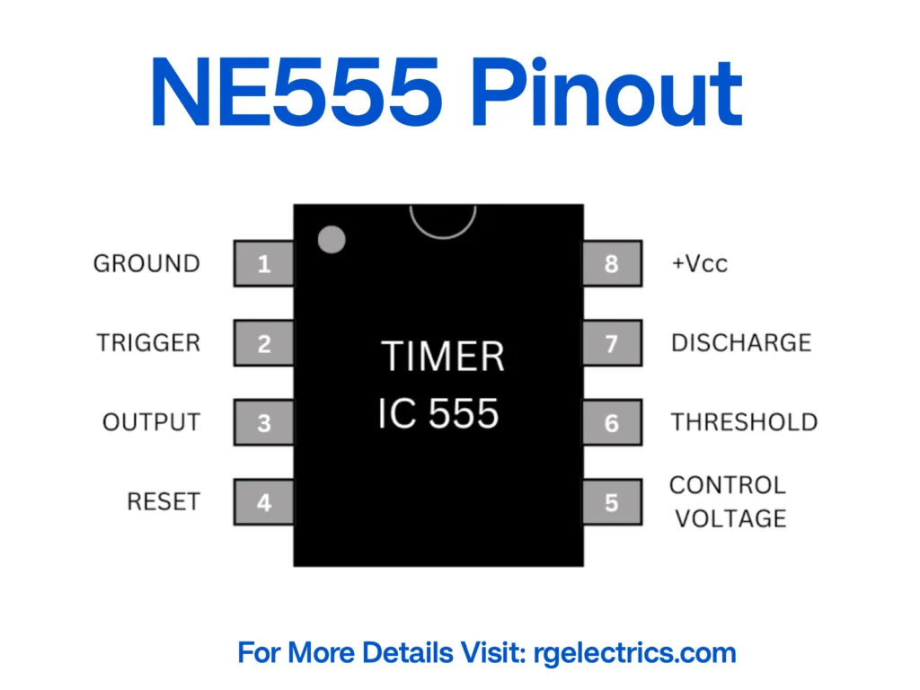
The NE555 Timer IC is an 8-pin integrated circuit widely used for generating clock pulses. The pin configuration is as follows:
- GND (Ground) – Connected to the negative terminal of the power supply.
- TRIG (Trigger Input) – Activates the output when voltage drops below 1/3 of VCC.
- OUT (Output) – Provides the timing pulse output to drive the LEDs.
- RESET – Active-low reset input (usually connected to VCC for normal operation).
- CTRL (Control Voltage) – Used for modifying the threshold voltage (left unconnected or grounded via a capacitor).
- THRESH (Threshold Input) – Monitors voltage levels to reset the timing cycle.
- DISCH (Discharge Pin) – Discharges the timing capacitor to reset the cycle.
- VCC (Power Supply) – Provides operating voltage (between 5V and 15V).
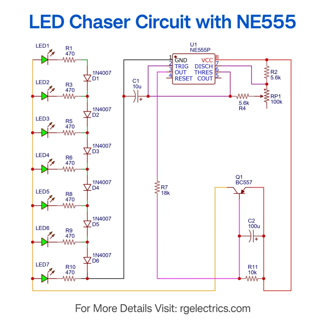
Circuit Diagram
Circuit Explanation
The LED chaser circuit operates on the principle of astable multivibrator mode of the NE555 Timer IC, which continuously generates square wave pulses at its output (pin 3). The operation is explained below:
- 555 Timer Clock Pulse Generation:
- The NE555 timer is wired as an oscillator to generate clock pulses at a frequency determined by the combination of R4 (5.6kΩ), RP1 (100kΩ), and C1 (10µF).
- The frequency can be adjusted using the potentiometer (RP1), which controls the speed of the LED chasing effect.
- LED Sequencing via Transistor and Diodes:
- The clock pulses from the NE555 output (pin 3) are fed to the BC557 PNP transistor, which acts as a switching element.
- The transistor inverts the pulse to drive the LED sequence.
- Diodes (1N4007) are used in series with each LED to control the flow of current and ensure a sequential lighting effect.
- Working Mechanism:
- When the timer IC sends a pulse, the transistor switches the LEDs in a sequential pattern.
- The capacitor C2 (100µF) smooths out fluctuations in the power supply, ensuring stable operation.
- As the clock pulses continue, the LEDs light up one after another, creating a chasing effect that resembles moving lights.
- Speed Control Mechanism:
- The potentiometer (RP1) changes the resistance in the RC timing circuit, affecting the frequency of oscillation.
- Increasing the resistance increases the time interval between pulses, slowing down the LED sequence, while decreasing it speeds up the effect.
Applications of LED Chaser Circuit
The LED chaser circuit is widely used in various real-world applications, including:
- Decorative Lighting: Used for festival decorations, stage lighting, and event displays.
- Advertising Displays: Applied in moving signboards and attention-grabbing advertisements.
- Running Light Indicators: Found in automotive applications such as sequential turn signals and brake lights.
- Educational Demonstrations: A great way to teach students about timing circuits, transistors, and LED sequencing.
- Gaming and Entertainment: Used in arcade machines and gaming consoles to enhance visual effects.
- Electronic Experimentation: Helps beginners understand the operation of oscillators and transistor-based switching circuits.
Conclusion
This Simple LED Chaser Circuit with NE555 is a fun and educational project that demonstrates the functionality of 555 timer IC in astable mode. By adjusting component values, you can customize the speed and pattern of the LED sequence to suit different applications. Whether you are a hobbyist or a student, this project serves as a great introduction to electronics and sequential lighting systems.