

Table of Contents
Introduction
The TDA8560 is a powerful audio amplifier IC designed for high-quality stereo sound applications. It is a dual 40W BTL (Bridge-Tied Load) amplifier, making it an ideal choice for automotive audio systems, home audio, and other high-power sound projects.
This amplifier IC is well known for its high efficiency, low distortion, and robust performance, making it ideal for use in car audio systems, home theater setups, and portable sound systems. It features built-in short circuit and thermal protection, ensuring reliable operation even under demanding conditions. Additionally, the low noise and minimal external components required make it a convenient choice for DIY audio enthusiasts and professionals alike.
The TDA8560Q can operate with a wide voltage range of +6V to +18V, making it highly versatile. It works in a Bridge-Tied Load (BTL) configuration, providing a powerful output without the need for additional output coupling capacitors or bootstrap capacitors. This results in an efficient and compact circuit design with superior sound clarity.
This guide explains the TDA8560 amplifier circuit, its components, and how it functions, giving you a complete understanding of its working principles and practical applications.
Components Detail
Below is a table listing the key components used in the circuit along with their specifications:
| Component | Value/Specification | Function |
|---|---|---|
| IC | TDA8560Q | Dual 40W BTL Audio Amplifier |
| Capacitor (C1, C2) | 220nF | Coupling capacitors for input signal |
| Capacitor (C3) | 100nF | Power supply noise filtering |
| Capacitor (C4) | 2200uF/50V | Power supply stabilization |
| Resistor (R1) | 10KΩ | Pull-up resistor for diagnostic out |
| Speakers | 4-ohm | Output speakers |
| Power Supply | +6V to +18V | Provides power to the amplifier |
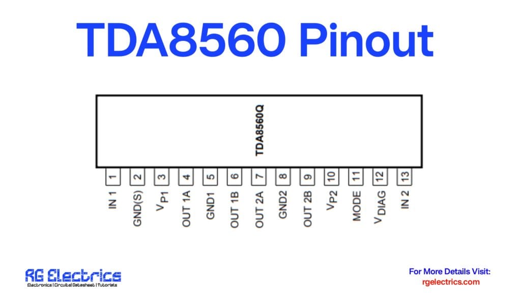
TDA8560 Pinout
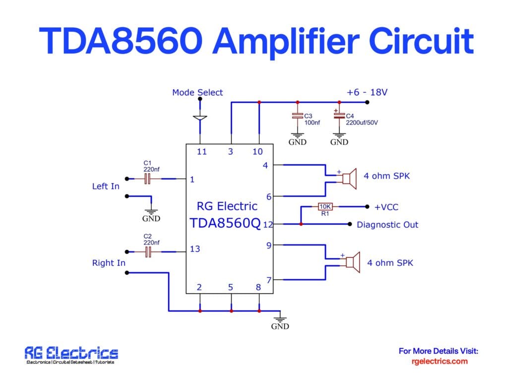
Circuit Diagram
Circuit Description
The TDA8560 amplifier circuit consists of essential components for input, power supply, and output. Below is an explanation of each section:
1. Power Supply
- The IC operates on a +6V to +18V power supply, typically from a 12V battery.
- C3 (100nF) and C4 (2200uF/50V) are used for power filtering and noise reduction to ensure stable operation.
2. Audio Input
- Two input channels, Left In and Right In, allow stereo audio signals to enter the amplifier.
- C1 and C2 (220nF capacitors) act as coupling capacitors to block DC components from the input signals.
3. Amplification Section
- The TDA8560Q IC receives input signals and amplifies them.
- It operates in a BTL configuration, meaning each speaker gets a full power output from both sides of the IC.
4. Output Stage
- Two 4-ohm speakers are connected at the output pins of the IC.
- The Bridge-Tied Load (BTL) design increases the output power while maintaining efficiency.
- R1 (10K resistor) and the Diagnostic Out pin help in fault detection and monitoring.
5. Mode Selection
- The Mode Select Pin (Pin 11) controls the amplifier’s operational mode.
- It can be used to enable or disable the amplifier as needed.
Features of TDA8560
- High Power Output: 40W per channel at 4-ohm load.
- Low Distortion: Ensures high-quality audio output.
- Short Circuit Protection: Protects against overheating and circuit faults.
- Low Noise Operation: Built-in noise suppression for clear audio performance.
Applications
- Car Audio Systems
- Home Stereo Amplifiers
- Portable Speaker Systems
- PA Systems and DIY Audio Projects
Conclusion
The TDA8560 audio amplifier circuit is a reliable and efficient solution for high-power stereo applications. Its easy integration, low distortion, and high efficiency make it a great choice for both professionals and hobbyists. Whether you are designing a car audio system or a home amplifier, this IC ensures excellent performance and durability.


wonderful issues altogether, you simply gained a logo new reader.
What could you suggest about your put up that you just made a
few days in the past? Any certain?