Table of Contents
Introduction
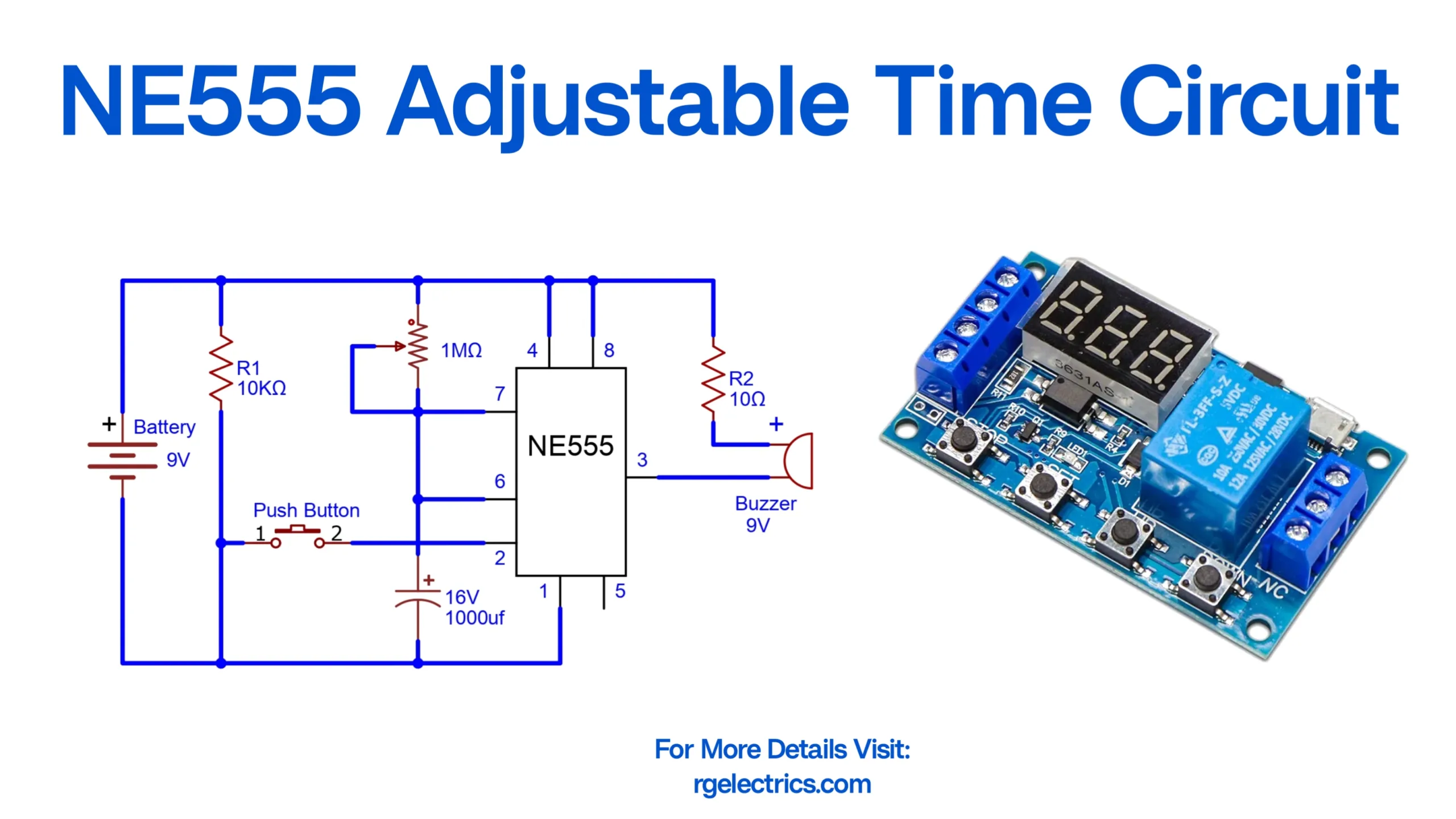
The NE555 Adjustable Time Circuit is a simple yet effective timer circuit used in various applications, including delay circuits, alarms, and timed switching operations. This circuit utilizes the NE555 Timer IC, a widely used and highly versatile component that can operate in monostable, astable, and bistable modes. In this design, the circuit functions in monostable mode, meaning that when the push button is pressed, the circuit generates a timed output pulse, which then activates a buzzer for a specific duration.

This article provides a detailed explanation of the circuit components, working principles, applications, and modifications that can be made to customize the delay duration.
Components List
Below is the list of essential components required to build this NE555 Adjustable Time Circuit:
| Component | Specification/Details |
|---|---|
| NE555 Timer IC | Used for generating the timing signal |
| Battery | 9V power supply source |
| Resistor (R1) | 10kΩ (Limits current to the circuit) |
| Resistor (R2) | 10Ω (Limits current to the buzzer) |
| Variable Resistor | 1MΩ (Adjusts the timing duration) |
| Capacitor | 1000µF, 16V (Determines timing duration) |
| Push Button | Used to trigger the circuit |
| Buzzer | 9V (Indicates the circuit is active) |
| Connecting Wires | For circuit assembly |
| PCB/Breadboard | For assembling the circuit |
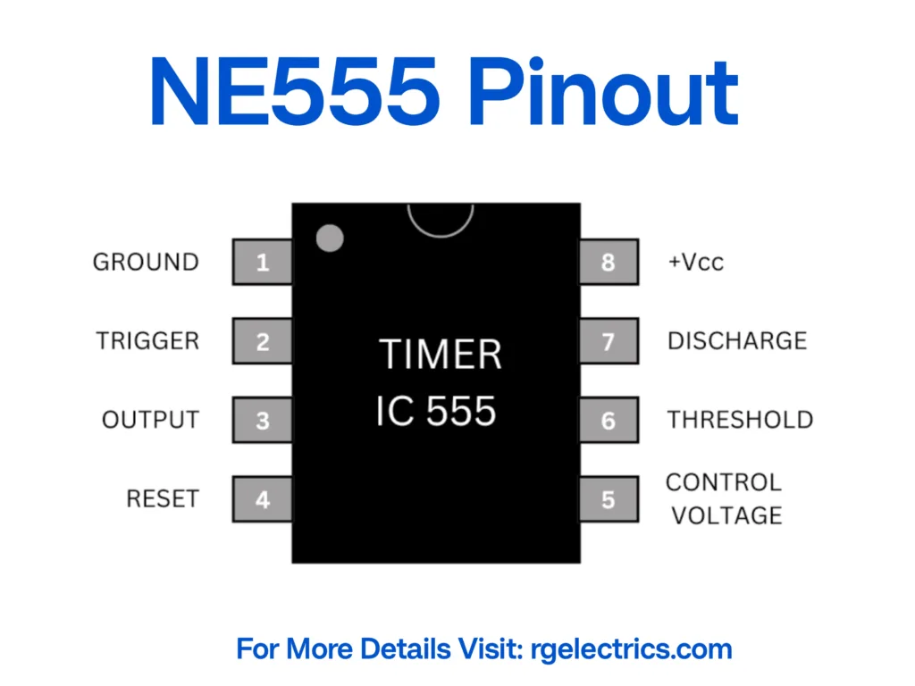
NE555 Pinout
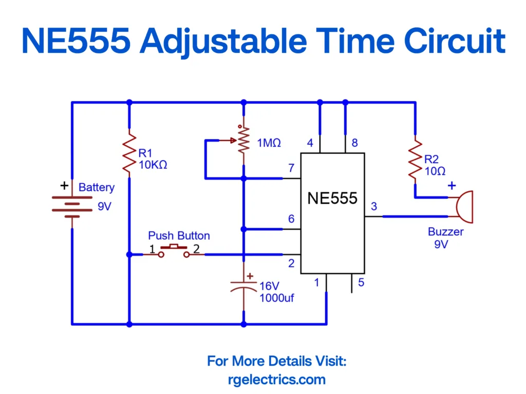
Circuit Diagram
Circuit Explanation
The NE555 Adjustable Time Circuit operates in monostable mode, where pressing the push button triggers a timed pulse. Here’s how the circuit works:
1. Triggering the Timer
- When the push button is pressed, it connects the trigger pin (Pin 2) of the NE555 to ground, initiating the monostable operation.
- This starts the timing sequence by charging the 1000µF capacitor, which controls the duration of the output pulse.
2. Timer Activation and Pulse Duration
- The 1MΩ variable resistor (potentiometer) and 1000µF capacitor together determine the time delay of the circuit.
- The output at Pin 3 of the NE555 remains high (ON state) until the capacitor charges to 2/3 of the supply voltage.
- The time duration (T) can be calculated using the formula: T= 1.1×R×C
- where:
- R is the resistance (variable resistor, 1MΩ)
- C is the capacitance (1000µF)
- Adjusting the variable resistor changes the resistance value, thus increasing or decreasing the time duration.
3. Output Signal and Buzzer Activation
- While the output (Pin 3) remains high, the buzzer is activated via R2 (10Ω resistor).
- Once the capacitor is fully charged, the output switches back low (OFF state), turning off the buzzer.
Applications of the NE555 Adjustable Timer Circuit
This circuit can be applied in various real-life scenarios, including:
- Automatic Alarms – Used in doorbells and security systems where an alarm sounds for a specific time.
- Kitchen Timer – Helps in setting time-based reminders for cooking.
- Game Timers – Used in board games where time-based turns are required.
- Fan Delay Off Circuit – Allows a fan to run for a preset duration before turning off.
- Photography Exposure Timer – Controls the duration of camera shutter exposure.
- Industrial Timing Applications – Used for timed switching of machines and conveyor belts.
Modifications and Enhancements
The circuit can be customized in various ways to suit specific applications:
- Changing the Timing Duration:
- The time delay can be increased or decreased by adjusting the values of the variable resistor (R1) or the capacitor (C1).
- Example: Increasing the capacitor value to 2200µF will double the timing duration.
- Replacing the Buzzer with a Relay:
- Instead of a buzzer, a relay can be used to control external appliances, allowing devices like lamps or motors to operate for a fixed time.
- Using a Digital Display:
- A 7-segment display or LCD screen can be integrated to show the countdown time.
- Battery-Powered vs. Adapter-Powered:
- The circuit can operate on a 9V battery, but for long-term use, a 9V DC adapter is a better alternative.
Conclusion
The NE555 Adjustable Time Circuit is a simple yet highly functional circuit that provides precise time delays for various applications. By adjusting the variable resistor and capacitor, the delay time can be easily modified, making it a versatile circuit for multiple uses such as alarms, timers, and automatic switching applications.
With simple modifications, this circuit can be enhanced to include relays, displays, and extended timing options, making it a valuable addition to any electronics project. Whether you are a beginner or an experienced hobbyist, this circuit serves as an excellent learning experience in understanding monostable mode operation of the NE555 Timer IC.