Table of Contents
Introduction:
The BC557 is a PNP bipolar junction transistor (BJT) primarily used for low-power amplification and switching applications in electronic circuits. It is a commonly used transistor in various consumer electronics, audio equipment, and signal processing systems.
Structure and Operation:
The BC557 is a PNP transistor, which means its three layers are arranged as: Emitter (P), Base (N), and Collector (P). In a PNP transistor, current flows from the emitter to the collector, and the current flow is controlled by the voltage applied to the base. When a small current flows from the base to the emitter, it allows a larger current to flow from the emitter to the collector, making it useful for amplification.
Key Characteristics:
- Polarity: PNP (Positive-Negative-Positive), meaning the transistor turns on when the base voltage is lower than the emitter voltage.
- Collector-Emitter Voltage (Vce): Typically 45V, making it suitable for low-voltage applications.
- Collector Current (Ic): The BC557 can handle up to 100mA of continuous current, ideal for small power devices.
- Power Dissipation: Maximum power dissipation is around 500mW, which helps in limiting heat in small circuits.
Typical Uses:
- Switching: The BC557 is often used as a switch in low-power applications, turning on or off small devices in electronic circuits.
- Amplification: It is used in signal amplification in audio circuits or other analog signal applications.
- Complementary Pairs: It is often used in complementary push-pull amplifiers in combination with NPN transistors like the BC547.
- Voltage Regulators: It can be used in low-power voltage regulators for stable output.
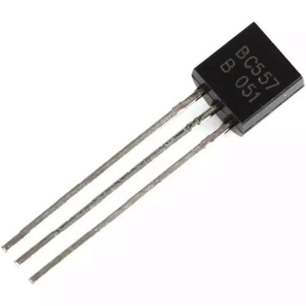
Package:
- Typically packaged in a TO-92 form, making it suitable for through-hole mounting in small circuits.
Basic Pinout:
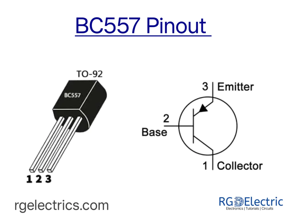
- Pin 1 (Emitter): Connected to the positive side of the power supply.
- Pin 2 (Base): The control terminal, which determines whether the transistor is on or off.
- Pin 3 (Collector): The output terminal, through which current flows when the transistor is on.
Common Applications:
- Audio amplifiers (as part of pre-amplifier or output stage).
- Simple switching circuits in control systems.
- Small relay drivers or indicator light controllers.
Working Principle:
- When the base is biased negatively with respect to the emitter, the transistor is turned on, allowing current to flow from the emitter to the collector.
- When the base is at a higher potential than the emitter, the transistor is off, and current does not flow through the collector-emitter junction.